Global Parameters
Global parameters include scalar and vector physical quantities (for example, 120.0 K or [0.0, 1.0, 0.0] m) that can be defined once and used in multiple objects. Another type of global parameter is a file, currently used for the Replace Parts operation in and in Design Manager.
Scalar and Vector Global Parameters
One application of this feature is using a key physical characteristic as a reference value. Other values can point directly to this reference value or be defined in terms of it. For example, in a boat simulation, the hull length could be used (directly or multiplied by a scale factor) in numerous other nodes.
Similarly, you can define a global constant like the mathematical value pi (3.14...). By defining a global parameter (for example, ${PI_CONSTANT}), you can use it repeatedly without entering the value again. This technique lets you keep the setting consistent; you do not have 3.14 specified for one object and 3.14159 for another. Because this parameter value is not defined on every cell, it can save significant system resources.
Another important use is design optimization – think of the global parameters as controls that can be conveniently adjusted over the course of multiple iterations of a simulation.
| Note | Only SI units are available for this feature. |
To set up a scalar or vector global parameter:
- To create the global parameter object, choose from the following techniques:
- Right-click the node and select Scalar or Vector from the New submenu.
- From within an object property that is a scalar or vector physical quantity,
select the property. An x button becomes
available. For example:
- For a scalar physical quantity, consider the Start Radius of a cone geometry
part.
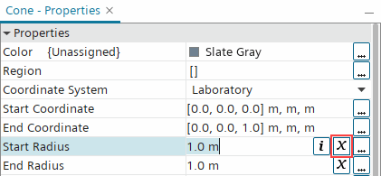
When you click x, the Start Radius changes from a constant to a parameter (in this example
${Cone Start Radius}).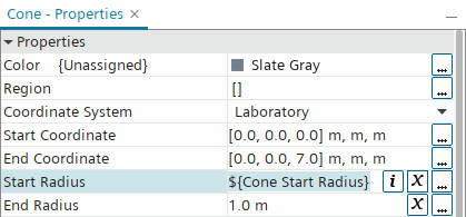
Within the node, a global parameter node (in this example Cone Start Radius) is added.
- For a vector physical quantity, consider the Value of the
Gravity reference value.
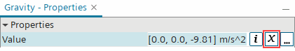
When you click x, the Value changes from a constant to a parameter (in this example
$${Gravity
											Value}
).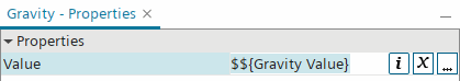
Within the node, a global parameter node (in this example Gravity Value) is added.
When you use this technique, the Value and Dimensions properties of the global parameter node are already defined based on the properties of the physical quantity object.
- For a scalar physical quantity, consider the Start Radius of a cone geometry
part.
- While working within the expression editor, create a global parameter by
selecting a parameter type from the New Parameter
drop-down list.
A New Parameter dialog appears in which you define the global parameter.
- If you created the global parameter within the node, rename the new node based on the type of quantity, for example MyStaticTemp for a scalar parameter.
- Set the value in the Value
property, either a constant or an expression.
Note Simulation parameter expressions can only reference other simulation parameters. References to reports or field functions are not allowed. If your parameter uses an expression, the Value property includes an i button that you can click to see the evaluated value of this expression. If your parameter references another parameter in the expression, the tooltip shows the value of the referenced parameter.
- Set a value in the
Dimensions property. Click
 (Custom Editor) and enter values in the dialog. These values are exponents.
For example, in the Scalar - Dimensions dialog for a scalar parameter, an entry of 1 for Temperature gives you the units K. An entry of 2 for Length gives you the units m2.
To apply a global parameter, follow a procedure similar to the example outlined below:
- Select a node that stores a scalar physical quantity, such as .
- Click
(Custom Editor) next to the
Value property.
- In the dialog that appears, for example
Static Temperature - Value, click
(Custom Editor) next to the
Definition property.
- In the definition dialog, apply the global parameter, which is listed in the
Variable column:
When you hover over the parameter with the mouse pointer, the value of the parameter appears in a tooltip and in the bottom left corner of the dialog.
- Clear the existing definition from the expression text panel near the top of the definition dialog.
- Double-click the parameter. Its definition appears in the expression text panel as
${MyStaticTemp}.

- Click OK in the definition dialog and then in the value input dialog.
The definition of the parameter appears in the property of the object, such as the Value property of the Static Temperature node.
File Global Parameters
In the current release, this feature is used in the Replace Parts operation in and in Design Manager.
To set up a File parameter:
- Right-click the node and select File from the New submenu.
- Rename the new node to distinguish the file, for example with the base file name.
- In the
File property, click
(Custom Editor) and navigate with the standard
Open dialog, or enter the file path manually.