Geometry Parts: Creating the Main Fluid Volume and Subtracting the Enclosure and Fan
Although you can create the main fluid volume using 3D-CAD, Simcenter STAR-CCM+ provides additional tools at the geometry parts level with which you can achieve the same goal. Using the part-level tools helps you differentiate between detailed and bulk geometry creation.
Here, you first create parts from the 3D-CAD model before creating a part shape that defines the outer fluid volume:
-
Launch
Simcenter STAR-CCM+ and load
foundationTutorial_6.sim.
You can either use the sim file that you saved from the previous tutorial, or load the sim file provided in the tutorials bundle. See Downloading the Tutorial Files from the Support Center Portal.
- Save the simulation as foundationTutorial_7.sim.
-
Create geometry parts from the 3D-CAD model:
The solid bodies from the 3D-CAD model are added as geometry parts.
-
Right-click the Scenes node and select .
A new geometry scene, Geometry Scene 1, is added to the Scenes node. This scene automatically displays all parts that are listed under the node.
-
Create a part shape for the surrounding fluid volume:
-
In the
Create Block Part panel, set the following parameters:
Parameter Setting Corner 1 [-0.250, -0.025, -0.200] m Corner 2 [0.150, 0.150, 0.200] m 
-
In the
Create Block Part panel, set the following parameters:
-
Split the surfaces of the block in preparation for the extruder mesher that you will set up in a later tutorial:
-
In
Geometry Scene 1, select the face that is upstream of the flow.

To help you identify the correct face to select, pay attention to the orientation of the direction axes in the scene. Select the face that lies on the plane with the largest X value. -
In the same scene, select the surface that is downstream of the flow.

To help you identify the correct face to select, pay attention to the orientation of the direction axes in the scene. Select the face that lies on the plane with the smallest X value.
The selected patches are split and added to the node. -
In
Geometry Scene 1, select the face that is upstream of the flow.
-
Subtract the graphics card and disc from the static region:
-
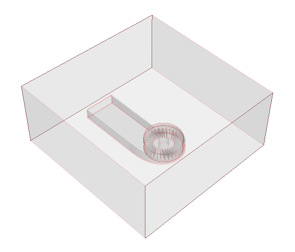
Modify the geometry scene to display only the parts that correspond to the simulation domain:
-
In the Properties window, click
 (Custom Editor) next to
Parts.
(Custom Editor) next to
Parts.
-
Click
 (Make Scene Transparent) to get a better view of the static region.
-
In the Properties window, click
-
To create a part contact between the static region and the rotating region, imprint these two parts together:
Part contacts define the connection between two part surfaces. The meshers aim to generate a conformal mesh at the contact, which then becomes an interface in the physics region.The two parts are imprinted together and a part contact is created between the two parts.
- Save the simulation.