Multi-Component Fluid: Time-Varying Boundary Conditions in a Dilution Pipe
Some analyses require that you set time-varying conditions on boundaries. User-defined field functions provide a method whereby you can do so.
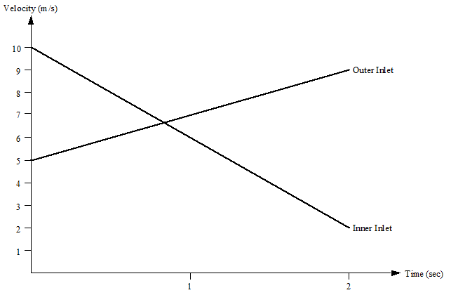
This tutorial resumes from the results that were obtained in the previous tutorial, "Multi-Component Fluid: Steady Flow in a Dilution Pipe." It solves the same problem except that, in this case, the velocities at the two inlet boundaries vary with time over a period of two seconds.
The velocity-time profiles at the inlets are shown below.

-
Launch
Simcenter STAR-CCM+ and load
foundationTutorial_dilutionPipe_Steady.sim.
You can either use the sim file that you saved from the previous tutorial, or load foundationTutorial_dilutionPipe_Steady.sim from the foundationTutorials folder.
- Save the simulation as foundationTutorial_dilutionPipe_Unsteady.sim
Most of the models have already been selected in the tutorial Multi-Component Fluid: Steady Flow in a Dilution Pipe. However, you must change the analysis type to unsteady:
- Right-click the node and choose
-
In the
Physics Model Selection dialog:
- From the Enabled Models group box, deselect Steady.
- From the Time group box, select Implicit Unsteady.
- Click Close.
- Inner Inlet:
- Outer Inlet:
-
Right-click the node and select .
The Properties window for the new function opens.
- Rename the field function node User Field Function 1 to Inner Inlet Velocity.
-
Select the Inner Inlet Velocity node and set:
- Definition to 10-4*$Time
- Function Name to Inner Inlet Velocity
- Create another scalar field function and rename its node to Outer Inlet Velocity.
-
Select the
Outer Inlet Velocity node and set:
- Definition to 5+2*$Time
- Function Name to Outer Inlet Velocity
- Select the node and set Method to Field Function.
- Click the right side of the Scalar Function property.
- In the dialog that appears, select the Inner Inlet Velocity field function node, then click OK.
- Open the node. Following the same procedure as described above, define the velocity magnitude at the outer inlet by the Outer Inlet Velocity field function.
- Save the simulation.
- Select the node and set Time-Step to 0.002 s.
- Select the node and set Maximum Physical Time to 2.0 s.
- Select the node and deselect Enabled.
- Select and set the X-Axis Monitor property to Physical Time.
- Save the simulation.
-
To run the simulation, click
 (Run) in the top toolbar.
If necessary, click the Residuals tab to bring the Residuals plot into view. The tabs at the top of the Graphics window make it possible to select any of the active displays for viewing.
During the run, it is possible to stop the process by clicking
 (Stop) in the toolbar. If you do halt the simulation, it can be continued later by clicking
 (Run). If left alone, the simulation runs for 2.0 s of physical time.
- Save the simulation.