Defining the Regions Layout
An essential part of the process in setting up your simulation is to define the relationship between geometry parts and regions, boundaries, and interfaces.
Geometry parts are used only to define the faces, edges, and vertices that make up the surfaces of the model. The simulation domain on which mesh is generated, and for which physics is solved, is defined using regions, boundaries, and interfaces. These simulation domain objects can be created automatically using the hierarchy of geometry parts.
If you import geometry into Simcenter STAR-CCM+, you can choose to interpret the geometry directly as regions, boundaries, and interfaces without going through geometry parts. This method was the default in earlier versions of Simcenter STAR-CCM+. However, the recommended approach is now to use geometry parts initially and assign them to the simulation domain after making any required changes to surface or part curve definitions.

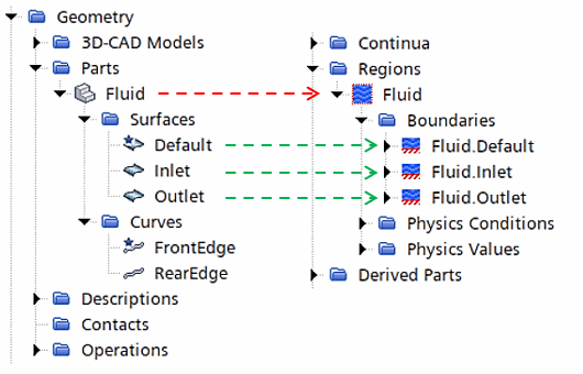
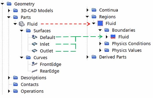
A part must be assigned to a region before its part surfaces can be assigned to boundaries within a region. The relationships do not need to be one-to-one; multiple parts can be assigned to the same boundary. The following mapping would also be valid, for example:

It is important to note that part contact information can only be used to generate interfaces automatically if all contacting parts are assigned to new regions in the same operation.