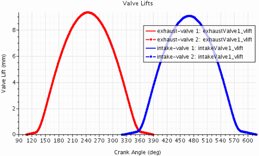
Valves Motion
Simcenter STAR-CCM+ In-cylinder models the motion of valves using valve lift curves.
A valve lift curve describes the offset of a valve from its closed position as a function of crank angle. For each valve, Simcenter STAR-CCM+ In-cylinder requires a valve lift curve in tabular form, where the first column lists the crank angle position in deg and the second column lists the according valve lift in mm.
The following table gives an example of a valve lift table:
107,0.0000
108,0.0037
109,0.0112
110,0.0187
111,0.0262
112,0.0337
113,0.0412
114,0.0487
115,0.0562
116,0.0637
117,0.0712
118,0.0787
119,0.0862
120,0.0937
121,0.1012
122,0.1087
123,0.1162
124,0.1238
125,0.1317
...
The table must provide data for the duration of the valve lift only and begin and end at zero lift. For the remainder of the cycle, Simcenter STAR-CCM+ In-cylinder automatically applies zero lift. When necessary, Simcenter STAR-CCM+ In-cylinder automatically applies the appropriate offsets to the crank angle data so that multiple cycles can be handled automatically.
Simcenter STAR-CCM+ In-cylinder allows you to modify the imported tabular data and preview the modified valve lift curve interactively.
The valve lift is calculated as:
VL = interpolateTablePeriodic(@Table("<tablename>"),"<column0>", LINEAR, "<column1>", ${Crank Angle Cycle} - <CA>/<DM> + <PA>, ${Cycle Length}/<DM>) * <LM> - <L>where:
interpolateTablePeriodic()periodically repeats the tabular data using piecewise-linear interpolation between the table values. See Interpolating and Differentiating Table Values.${Crank Angle Cycle}is the cycle wrapped crank angle in deg (repeats 0 to cycle length).${Cycle Length}is the length of the cycle—720 deg for four-stroke and 360 deg for two-stroke engines.<DM>is the specified Duration Mutliplier.<PA>is the specified Profile Anchor in deg.<CA>is the specified Cycle Anchor in deg.<LM>is the specified Lift Multiplier.<L>is the specified Lash in mm.
For information, on the specified values, see Engine Reference—Valve Dialog.
Valves Opening and Closing
Simcenter STAR-CCM+ In-cylinder controls the opening and closing of the valves using valve curtain interfaces. A valve curtain interface is a curved surface area that is located on the Face surface of a valve and separates the cylinder volume from the respective port volume.
The following image shows the valve curtain interfaces for a four-valve cylinder:
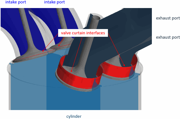
Simcenter STAR-CCM+ In-cylinder captures the valve opening and closing events at a default valve lift of 0.1 mm. As long as the valve lift exceeds that value, the valve curtain interface allows mass, momentum, and energy to pass from one volume to another. When the valve lift drops to that value or below, the adjacent fluid treats the valve curtain interface as an impermeable adiabatic slip wall.