Field Function Interpolation and Interfaces (FV)
For finite volume meshes, understanding how Simcenter STAR-CCM+ deals with field function data is important for avoiding non-physical results in post-processing at an interface, and to appreciate the difference that smoothing makes when it is applied.
Background
In Simcenter STAR-CCM+, for finite volume meshes, most variables are solved and stored at cell centers. For some quantities on some boundaries, variables are stored additionally at the centroid of boundary faces, for example, pressure on an inflow boundary.
Boundaries
To render, plot, or compute data on boundary faces for quantities that have no storage on the boundary face, Simcenter STAR-CCM+ interpolates the cell center data from the adjacent region using nearest-neighbor interpolation.
If you want to be sure that you are viewing data from the cell centroid adjacent to a boundary, you must create a user field function that references the existing field function but for which you activate the property, Ignore Boundary Values. See Ignoring Boundary Values.
Interfaces
When interpolating a field function, Simcenter STAR-CCM+ presumes that all field functions are real-valued quantities that are continuous across a direct interface. While this presumption is valid for most physical quantities of interest (such as Temperature and Pressure), it is not valid for all field functions available in the simulation. Notable examples of discontinuous and integral-valued field functions include PartitionId and CellPartIndex. When you visualize or otherwise use integral-valued field functions on a location that requires interpolation, non-integral values can result—especially at an interface.
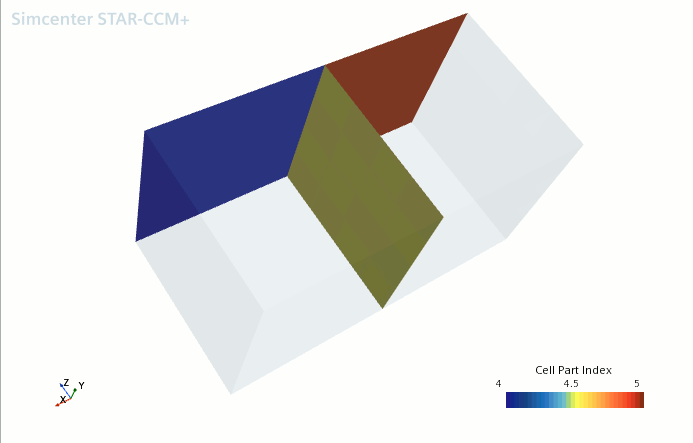
In the simple example below, two boxes are connected by an interface. The boxes have Part IDs 4 and 5, respectively. The scene shows the CellPartIndex field function plotted at one unconnected surface as well as the interface between the two parts. When viewing the function on the surfaces adjacent to each volume individually, the interpolation behaves as expected—the value of CellPartIndex is taken from the adjacent cell. However, when viewing the function on the interface, the value of CellPartIndex is 4.5 because this value is the average (interpolated) value of the cell values on either side of the interface.

Interpolation of field functions is a local operation, and for real-valued continuous quantities, the error due to interpolation is correlated with the quality of the mesh. As the mesh becomes finer, the difference between vertex values and cell values decreases, with the limit of local error going to zero. However, because the interpolation is local, some reports can have different results when comparing smoothed and non-smoothed versions, even for quantities that are based on the mesh, and for an increasingly fine mesh. A particular example is the sum report of Area: Magnitude. This report is expected to show differences between the smooth and non-smoothed versions for any mesh regardless of how fine the mesh is.
Smoothing
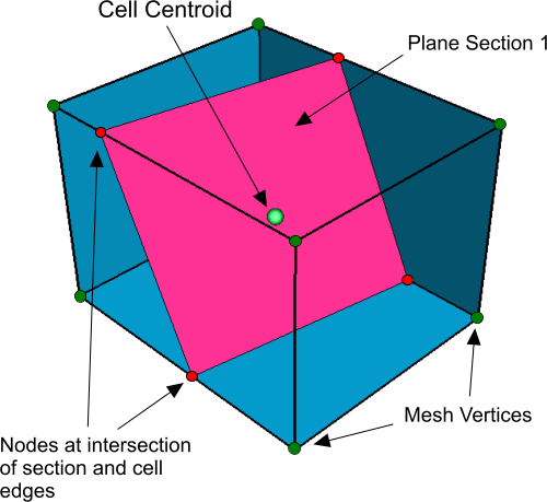
When smoothing is activated on a plot, report, or displayer, Simcenter STAR-CCM+ smooths field function values by interpolating the cell center values to vertices using a first-order method. In the case of reports, these vertex-interpolated values are used to perform the computation rather than the cell center values. If a derived part cuts through cells in a mesh, the value of the field function at extraction (intersection) points is interpolated from these vertex values as shown in the following diagram:

By default, the method used to interpolate field functions from cell centers to vertices uses an unweighted average of all the adjacent cell values. For user-defined field functions, you can change this method to a weighted average using the inverse distance to cell centers. To use the weighted method, select the field function node under and activate its Inverse Distance Weight property. See Interpolating Field Functions Using Inverse Distance Weighting.