Example Workflows
Several automation processes are possible using simulation operations in Simcenter STAR-CCM+.
Multi-Timescale CHT Simulation
- Problem
- How to switch between solvers in a fluid continuum and a solid continuum alternately until the overall solution converges.
- Solution
-
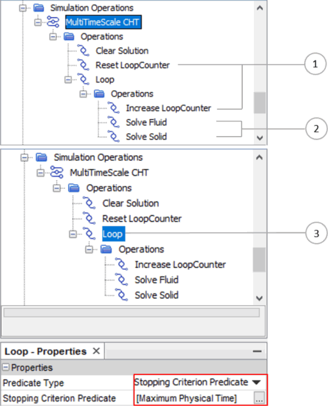
Define a Loop operation that includes two Solve Physics operations—one for each continuum. Each Solve Physics operation runs the solvers for its associated continuum until their solver specific stopping criteria are satisfied. The loop stops once the global stopping criterion is satisfied.

- Discussion
-
- Counting outer loops:
- Create a scalar parameter under the node and name it as LoopCounter or similar.
- Within the simulation operation sequence, add a Set Scalar Parameter operation and rename it to Reset LoopCounter. In the definition, set the initial value of the LoopCounter to 0.0.
- In the child sequence of the loop operation, add another Set Scalar Parameter operation that increases the LoopCounter parameter in the loop. In the definition, use the expression $LoopCounter+1.
- You can use this outer loop count as an annotation in an appropriate scene.
- Solving alternate continua sequentially:
- For the solvers associated with the models in each continuum, define solver-specific stopping criteria. For example, you can define the following:
- A Fixed Steps stopping criterion within the steady solver associated with the fluid
- Fixed Physical Time and Maximum Inner Iterations stopping criteria for the implicit unsteady solver associated with solid
- In the child sequence of the loop operation, include one Solve Physics for the defined fluid continuum and rename it to something like, Solve Fluid.
- Include another Solve Physics for the defined solid continuum and rename it to something like, Solve Solid.
- The Solve Physics operations step until the solver-specific stopping criteria in the corresponding solvers are satisfied.
- For the solvers associated with the models in each continuum, define solver-specific stopping criteria. For example, you can define the following:
- Applying stopping criterion predicate:
- Select the global stopping criterion you defined under the Stopping Criterion node. For example, this selection could be the node.
Note To change the order of single operations in the chain, right-click and select Reorder... For the detailed procedure, refer to the Simulation Operations: Multi-Timescale Conjugate Heat Transfer tutorial.
- Counting outer loops:
Adjoint Shape Optimization
- Problem
- Optimize a geometry by running the primal solver, adjoint solver, and the mesh deformation solver sequentially. The number of optimization cycles is controlled by a scalar parameter.
- Solution
-
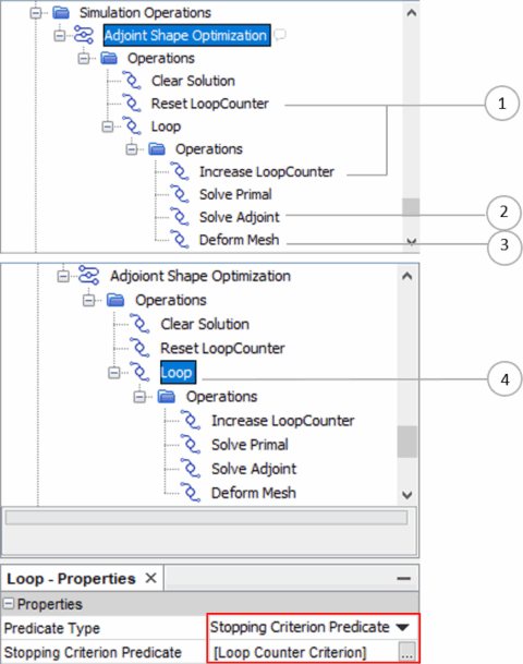
Define a Loop operation including one Solve Physics operation for primal, one Solve Adjoint operation, and one Deform Mesh operation. Set the loop to stop when the user-defined number of optimization cycles is reached.

Note Before you launch the simulation operation seuqence, define the Morpher Displacement for the boundaries you want to optimize. The displacement is usually a function of surface sensitivity, for example $${CumulativeMorpherDisplacement}+${factor}*$${Adjoint1::Surface Sensitivity}. Therefore, the surface sensitivity computation must be activated in the Solve Adjoint operation. The factor must be properly selected to avoid over deformation of the volume mesh. The factor varies for different applications. For more details, refer to Setting Up a Shape Optimization. - Discussion
-
- Counting outer loops: as for the Multi-Timescale CHT Simulation example above.
- Solving adjoint solver:
- In the child sequence of the Loop operation, include one Solve Adjoint operation. This operation becomes available when the adjoint model is selected in a physics continuum. Activate the option Compute Surface Sensitivity since you need surface sensitivity to proceed with the optimization step.
- Deform mesh:
- This operation deforms the volume mesh with the Morpher Displacement you defined under .
- Applying the Loop Counter in a stopping criterion predicate:
- Create an expression report for the parameter LoopCounter.
- Create an monitor from the expression report.
- Create a stopping criterion from the monitor and rename it to
Loop Counter Criterion.
- Use Maximum as the criterion option.
- Set the maximum value to 5.
- Select the Loop Counter Criterion as a stopping criterion predicate. The simulation operation sequence runs until 5 cycles of shape optimization are complete.
Moving Box using Morpher and Remeshing
- Problem
-
Move a box through a channel over time using mesh morphing and remeshing. During successive morphing, the mesh quality decreases while the displacement increases. A remesh must occur when the cell quality falls below a certain value.

- Solution
-
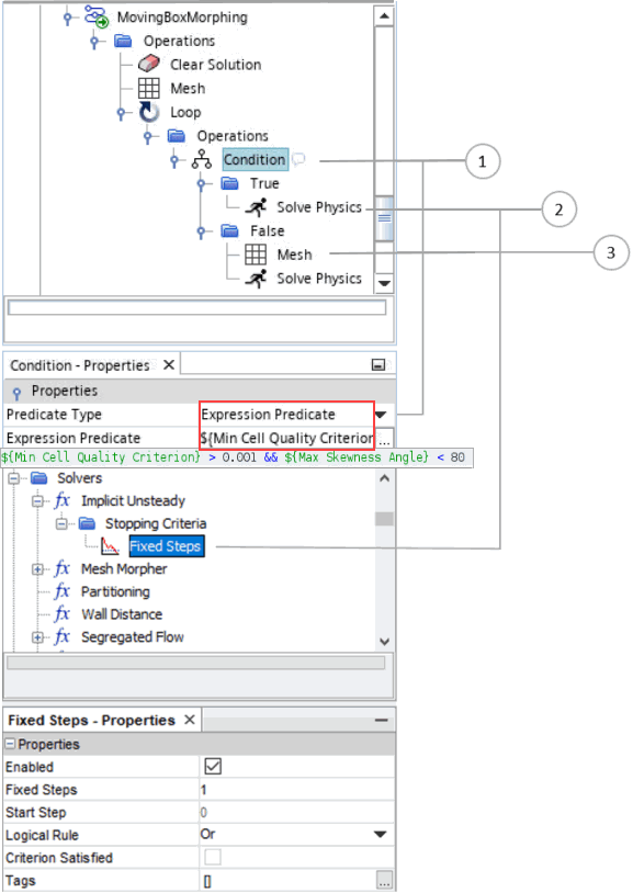
Define a combined mesh quality check as the predicate of a Condition operation. If the predicate evaluates to false, activate a remesh. In order to execute remeshing at the current position of the box, and not at the initial position, you include a Transform operation in the meshing pipeline with the type set to Motion. Then, you choose the same motion for the Transform operation as you apply to the box in the channel. Every time the remesh is launched by the Mesh operation, the mesh pipeline updates to include the motion transform.


- Discussion
-
- Condition and Predicate:
- Define the mesh quality criteria expression including, for example, minimum Cell Quality and maximum Skewness Angle. These criteria differ according to geometry and application.
- For this example, you create one report to output the minimum cell quality value, ${Min Cell Quality Criterion}, and another report for the maximum skewness angle value, ${Max Skewness Angle}. These reports consider all the cells.
- Select Expression Predicate as the predicate type and input the expression ${Min Cell Quality Criterion} > 0.001 && ${Max Skewness Angle} < 80. This predicate evaluates true only if both inequalities hold.
- If the predicate evaluates true, the implicit unsteady solver runs for 1 step. The flow around the moving box in the tunnel is solved.
- If the predicate evaluates false, the mesh operations you define under are executed. A new mesh with the current position of the box is generated. Afterwards the implicit unsteady solver runs for 1 step. This solver execution step is necessary for updating the reports that check the cell quality. If you omit the solver stage after the meshing stage, the reports are not updated, and the sequence would enter a continual remeshing loop.
- Solver specific stopping criterion:
- Here, the example defines a Fixed Steps criterion for the implicit unsteady solver, which allows it to run for one time step only.
- Mesh operation:
- Executes the operations defined under the node.
- Transform Motion (within the node):
- Translates the box part with the Transform operation, whose transforms include a Motion transform. Refer to Transform Motion for more details.
- When you create the Transform operation, add the transform type, Motion, and set its Motion property to point to the same Translation motion (in this example) that is applied to the box in the channel. This motion is defined under the node.
- The current position of the box is updated when the Mesh operation executes.
- Condition and Predicate: