Basic 3D-CAD: Define Fluid Volume for Rotating Fan and Subtract the Blades
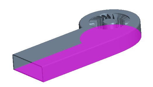
Modeling anything with a moving part, such as the graphics card fan, requires at least two simulation regions. One region rotates to model the motion of the fan, while the other region remains stationary to represent the remaining air. Here, you create the rotating region in 3D-CAD.
To create the rotating region:
-
Launch
Simcenter STAR-CCM+ and load
foundationTutorial_5.sim.
You can either use the sim file that you saved from the previous tutorial, or load the sim file provided in the tutorials bundle. See Downloading the Tutorial Files from the Support Center Portal.
- Save the simulation as foundationTutorial_6.sim.
- Resume the 3D-CAD model.
-
Draw a sketch around the fan:
-
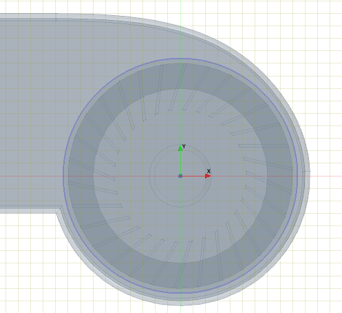
Select the bottom face in the cavity of the enclosure, as shown below, and select
.
-
Draw a circle with a radius of 47 mm and centered around the origin.
-
Select the bottom face in the cavity of the enclosure, as shown below, and select
.
-
Create the body for the rotating region:
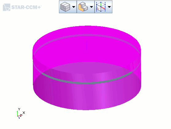
- Right-click Rotating Region Outline and select Extrude.
- Set Direction Type to Reverse.
- Set Distance to 35 mm.
- Set Body Interaction to None to create a separate body from this operation.
- Click OK.
- Rename to Rotating Region.
- Expand the Body Groups node and rename the new body to Rotating Region.
-
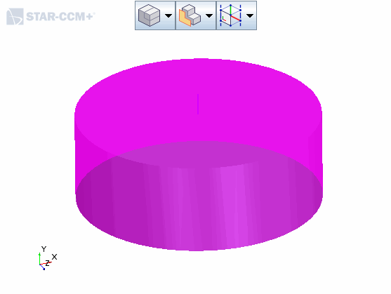
Create a copy of the rotating region to subtract from the static region in the next section:
- Right-click and select Duplicate.
- In the Duplicate Bodies panel, click OK.
- Rename to Disc.
- Rename to Duplicate Rotating Region.
-
Subtract the fan and enclosure from the rotating region:
-
Rename the outer faces of the rotating region body:
-
In the
3D-CAD View scene, select the large top and side faces in the scene. Do not select the faces in the narrow gap or the bottom face.
-
In the
3D-CAD View scene, select the large top and side faces in the scene. Do not select the faces in the narrow gap or the bottom face.
-
Rename the outer faces of the disc body:
-
In the
3D-CAD View scene, select the top and side faces in the scene. Do not select the bottom face.
-
In the
3D-CAD View scene, select the top and side faces in the scene. Do not select the bottom face.
-
Right-click a blank space in the 3D-CAD View
scene and select .
- Save the simulation.