Basic 3D-CAD: Sketching a Profile with Curves and Splines
Sketch profiles can contain a combination of simple curves, such as arcs and splines. Split and trim tools allow you to remove unwanted curves within a shape. Here, you create a sketch for the fan enclosure.
The fan is positioned 2 mm above the bottom of the fan enclosure. The fan enclosure is 2 mm thick.
To sketch the fan enclosure:
-
Launch
Simcenter STAR-CCM+ and load
foundationTutorial_3.sim.
You can either use the sim file that you saved from the previous tutorial, or load the sim file provided in the tutorials bundle. See Downloading the Tutorial Files from the Support Center Portal.
- Save the simulation as foundationTutorial_4.sim.
- Resume the 3D-CAD model.
-
Create a transform sketch plane to hold the sketch of the enclosure:
Create the sketch for the card enclosure:
- In the 3D-CAD View scene, right-click the visible sketch plane and select Create Sketch.
-
To view the sketch from the top of the card, from the
Vis toolbar, click
 (Save-Restore-Select Views) and select
.
-
Click
 (Create Circle) and draw a circle with center at the origin.
-
Set a fixation constraint on the center of the circle and add a
Radius dimension to the circle, with a radius of
52 mm.

-
Click
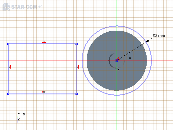
 (Create Rectangle) and draw a rectangle to the left of the circle.
-
Dimension the rectangle so that the vertical edge is
80 mm tall and the horizontal edge is
150 mm long.
If the rectangle moves away from the circle, you can click and drag it closer to the circle.
-
Make the top-right point of the rectangle coincident with the circle:
- Multi-select the point at the top-right corner of the rectangle and the edge of the newly created circle.
- Right-click a selection and choose Apply Coincidence Constraint.
-
Multi-select the bottom-right corner (point) of the rectangle and the center of the circle and set a vertical distance of 65 mm between these points.
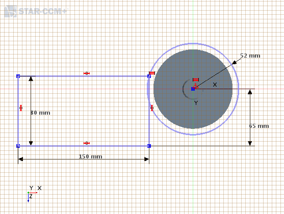
- Using the line tool, create a line between the top-right corner of the rectangle and the center of the circle.
-
Create another straight line that starts from the center of the circle and extends beyond the circle to the right.
Apply a horizontal constraint to this line.
-
Select both straight lines and set them as construction lines.
You will use these lines for trimming the circle.
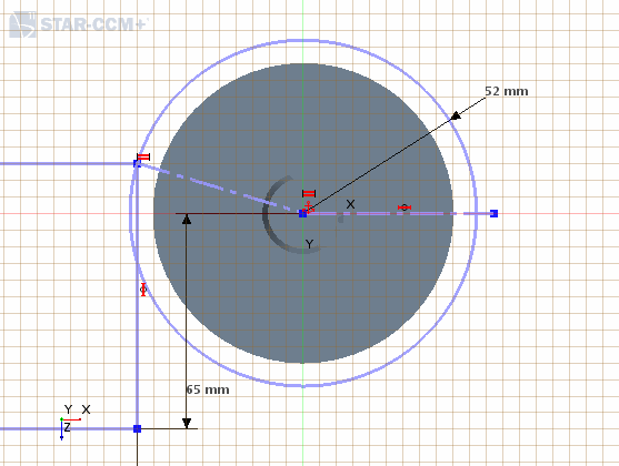
-
Using the <Ctrl> key, multi-select the circle and the two construction lines, in that order. Right-click one of the lines and select
Split for Trim.
The order in which you select the sketch entities is important and defines what entity is cut. The entity that you select first is the target. All subsequent selections are the tools that cut the target.The radius dimension for the circle is consumed by this action.
-
Select the bottom part of the circle and delete it using the <Delete> key.
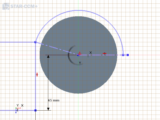
-
Select the right, vertical, edge of the rectangle and set this as a construction line.
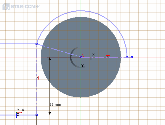
-
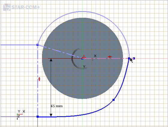
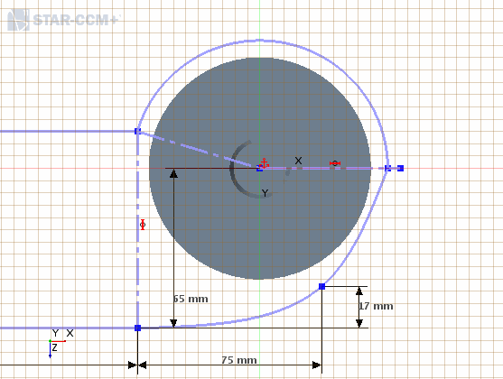
Draw a spline that links up the bottom edge of the rectangle to the right edge of the circle:
-
Make the spline tangent to the circle and to the bottom edge of the rectangle:
- Select the spline and the circle.
- Right-click a selection and choose Apply Tangent Constraint.
- Do the same between the bottom edge of the rectangle and the spline.
-
As a result of some actions, the sketch may move or change. While setting the tangent constraint, the split circle detached from the horizontal construction line. Make some final adjustments to the sketch:
- Select the right point on the split circle and the horizontal construction line and add a Coincidence Constraint.
- Add a Radius dimension with a radius of 52 mm to the split circle.
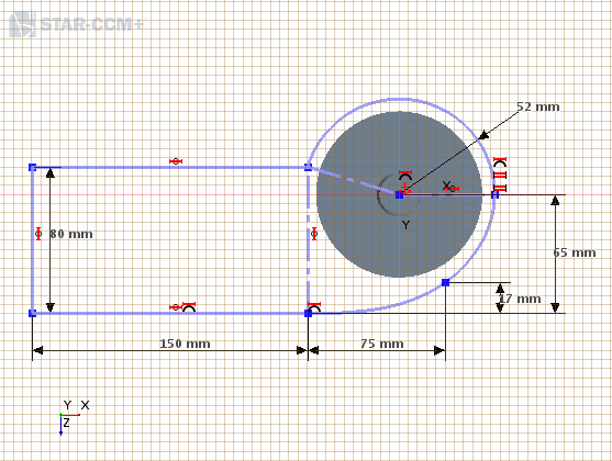
- Click OK to complete the sketch.
- Rename to Enclosure Sketch.
- In the 3D-CAD View scene, right-click the sketch plane and select Hide.
- Save the simulation.
 (
(