Basic 3D-CAD: Creating the Enclosure Solid Shell
In cases where you create the wetted volume first, Simcenter STAR-CCM+ allows you to surround the volume with a solid shell of specified thickness. This additional solid is then available for simulations that model phenomena in both solid and fluid materials.
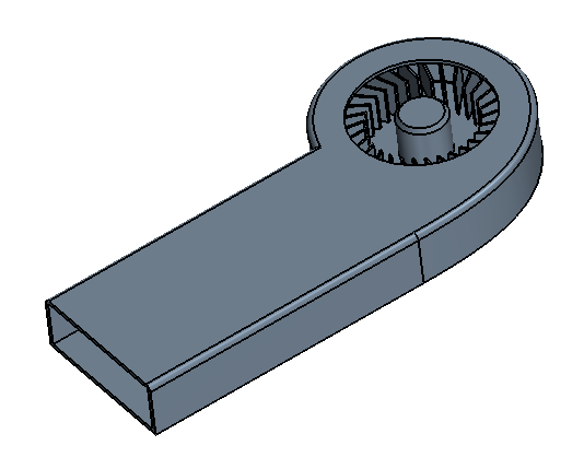
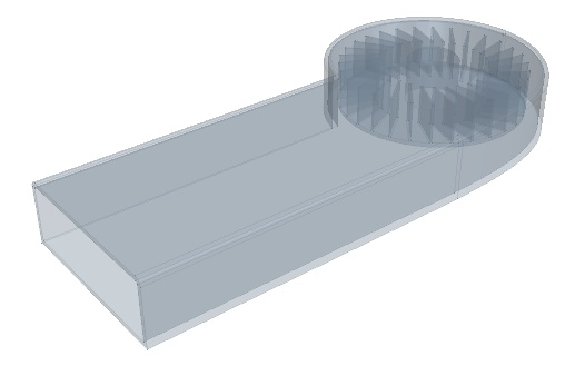
Create the solid body for the graphics card enclosure and thereafter expose the fan within the enclosure.
-
Launch
Simcenter STAR-CCM+ and load
foundationTutorial_4.sim.
You can either use the sim file that you saved from the previous tutorial, or load the sim file provided in the tutorials bundle. See Downloading the Tutorial Files from the Support Center Portal.
- Save the simulation as foundationTutorial_5.sim.
- Resume the 3D-CAD model.
-
Extrude the enclosure sketch to form a solid body:
-
Set
Method to
Up To Face and select the top face on the graphics card fan hub.
-
Click
OK.
-
Set
Method to
Up To Face and select the top face on the graphics card fan hub.
-
Add a fillet to the top edge of the enclosure:
-
Click
OK.
-
Click
OK.
-
Shell the enclosure:
-
In the
3D-CAD View scene, select the face that corresponds to the exhaust of the enclosure.
This face is removed from the shelling operation so that the enclosure has an opening. -
Click
OK.
-
In the
3D-CAD View scene, select the face that corresponds to the exhaust of the enclosure.
-
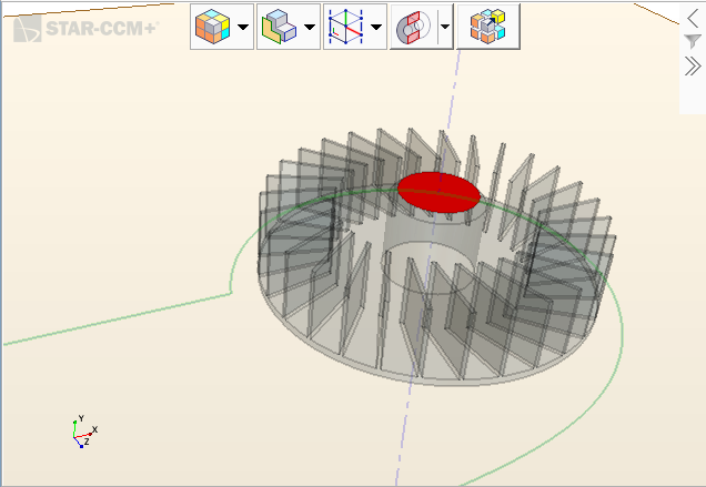
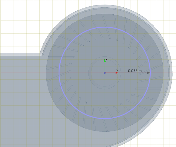
Draw a sketch for the fan opening:
-
Draw a circle about the fan axis that has a radius of
35 mm.
Activate scene transparency so that you can see the fan.
-
Draw a circle about the fan axis that has a radius of
35 mm.
-
Cut out the opening for the fan:
- Expand the Body Groups node and rename the new body to Enclosure.
- Save the simulation.