Periodic Interface Topology
The boundaries of a periodic interface are physically separated in space but can be mapped from one to the other through some constant rotation and/or translation. The periodic interface represents a cyclic repeat of information across the boundaries, so fluxes that cross one boundary are transformed and applied to the other.
This effectively approximates a repeating geometry. For example, you can model an infinitely long pipe by using a short segment of the pipe and applying a periodic interface between the two ends.
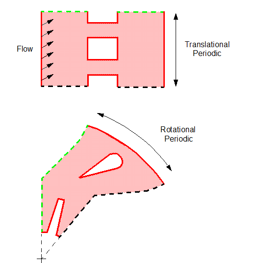
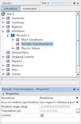
To define a periodic interface, set the perimeter of one boundary to be coincident with the transformed perimeter of the periodic matching boundary. The figures below show examples of periodic interfaces as applied to geometries that repeat in a translational and rotational manner. The green and black dashed lines in each case represent the location of the periodic interface boundary pair. For each pair, the shape and size of the boundaries match, and they are separated by a given vector or angle. The translation vector or rotation angle are calculated automatically by Simcenter STAR-CCM+, and are properties of the interface Periodic Transformation node.

When you use a periodic interface with the surface remesher, tetrahedral, polyhedral, or thin meshers, the mesher produces a conformal mesh on each side of the interface. In other words, if successful, the two boundaries when mapped from one to the other match identically in terms of the vertex locations and face topologies. This results in a higher-quality mesh definition for the analysis stage.
Typically, the two sides of the interface are the same. However, in some cases the two sides can be different. For example, one side can consist of two patches/CAD faces, while the other side consists of just one patch/CAD face, resulting in the internal edge between them being different. An internal edge will be dropped if it fails to mate with an internal edge on the other side of the interface. In the case of CAD faces, the CAD mapping would also be dropped. The aim is to keep the faces conformal, if at all possible, by dropping less important criteria. In the above example, the less important criteria are mapping to CAD and internal feature edges.
The option to produce a conformal mesh is automatically initiated when a periodic type interface has been created and one of the above meshing tools is used thereafter. Attempts to produce a conformal mesh are made both during the surface remeshing stage and during volume mesh generation. This means that if a prepared surface mesh is imported from another source and used directly for volume mesh generation (without first resurfacing) then a conformal periodic boundary pair is still achievable within the bounds of the scheme.
The conformal mesh mapping is limited to rotational, translational, or mixed (roto-translational) cases where a boundary pair (within the in-built tolerance) is possible. If a successful mapping is found, then the transformation matrix, number of vertex pairs and face mappings is displayed in the Output window.
If a transformation matrix cannot be extracted, or mesh conformity is not satisfied between the periodic boundary pair, then a warning message is printed in the Output window that includes the location of where these problems are.
In this instance, the meshing scheme still produces a mesh but reverts to being non-conformal, exactly as if the periodic boundary pair did not exist. The absence of a periodic match can also be confirmed by looking at the number of faces belonging to each boundary in the periodic pairing using the node for the mesh. If the number of faces is different, then the mapping was unsuccessful.
If the automatic surface repair option for the surface remesher has been activated, then periodic boundaries are excluded from this operation. Take care when modifying the surface mesh by hand once the surface remesher has been run as changes to boundaries belonging to the periodic pairing are not preserved when it comes to the volume meshing step of the process.

These values are automatically “locked” for the interface node to prevent recalculation during further meshing operations. To change the values, untick the Locked option. The angle and translation is recalculated during meshing.

The meshing process still continues but ultimately leads to a non-conformal mesh being produced during intersection. If a conformal volume mesh is critical then review the periodic transformation property values for errors carefully. It is also recommended that a conformal surface mesh is produced first to guarantee that the volume mesh is also conformal for the periodic interface. That is, run the surface remesher first with the interface and properties defined fully before running the volume mesher.
Periodic Transformation Properties
- Periodicity
- Sets the type of geometrical
transformation that must be applied to vertices of the secondary boundary so
that they coincide with those of the primary boundary. The options are:
- Rotational+Translational
- Rotational
- Translational
- Axis of Rotation Specification
- You can either choose Specify axis to define a unique axis for this interface using an Axis child node, or else Use region's reference axis instead. In case of the latter option, the axis properties are defined in the node. When the periodic interface is applied to boundaries from two separate regions, the region axis from the primary boundary (Boundary-0) is used.
- Rotation Angle (deg)
- Translation (m)
- Computed transformation angle and translation distance between vertices on either side of the periodic interface.
- Locked
- Lock applied by the first mesh operation that calculates the transformation properties.