Gasoline Engine: Charge Motion
Simcenter STAR-CCM+ In-cylinder provides methods for predicting the charge motion in an internal combustion engine, including the injection of liquid fuel, the subsequent evaporation and mixing process, and the formation of fuel film on the engine walls.
In this tutorial, you investigate the spray formation resulting from a direct fuel injection into a single engine cylinder. The fuel composition is as follows:
| Fuel Component | Mass Weighting |
|---|---|
| Iso- (Isooctane, 2,2,4-Trimethylpentane) | 0.6 |
| (Toluene) | 0.35 |
| (n-Heptane) | 0.05 |
After injection, the fuel droplets mix with the in-cylinder gas and start to evaporate to form a flammable mixture. The goal of this tutorial is to predict the mass of vapor arising from the injected fuel and the liquid and vapor spray penetration. Additionally, you analyse the fuel/air equivalence ratio in the cylinder and the formation and transport of fuel film on the cylinder walls.
The engine geometry, the operating conditions, the initial and boundary conditions, and the motion of the piston and the valves are the same as introduced in the Gasoline Engine: Motored tutorial.
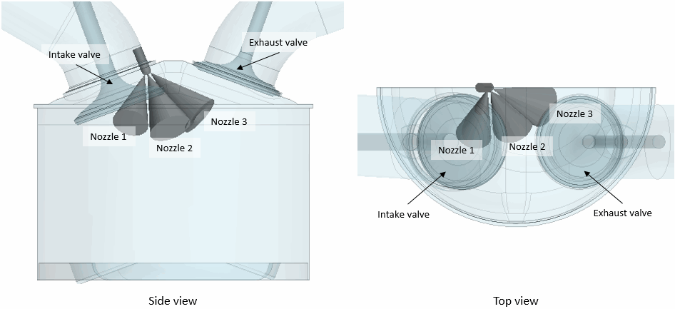
For the half engine model, you create a fuel injector on the symmetry plane and position it close to the intake valve. Three nozzles on the tip of the injector introduce the fuel into the cylinder—one hollow cone nozzle and two solid cone nozzles. One of the solid cone nozzles is oriented such as to direct its spray of fuel droplets towards the intake valve.

For all three nozzles, the hydraulic diameter of the nozzle hole is 0.2 mm and their cone angles are as follows:
| Nozzle | Outer Cone Angle | Inner Cone Angle |
|---|---|---|
| Nozzle1 | 30.0 deg | 0.0 deg |
| Nozzle 2 | 35.0 deg | 0.0 deg |
| Nozzle 3 | 33.0 deg | 15.0 deg |
The simulation starts at 300 deg crank angle. The fuel injection starts at 420.0 deg crank angle and ends at 469.41 deg crank angle.
You specify the injection conditions in the form of tables that describe the fuel mass flow rate and the injection temperature as functions of crank angle. To specify the diameter of the injected fuel droplets, you import a table that describes the distribution of the droplet diameter using a cumulative distribution function (CDF).
Starting from the final Gasoline Engine: Motored simulation file, you clear the mesh and re-run the simulation using automatic time-step control. For charge-motion simulations, automatic time-step control adjusts the time-step size based on the preset valve lift thresholds and on the start and end of fuel injection.
After the run, you analyze the simulation results using the charge-motion specific post-processing capabilities that are available in Simcenter STAR-CCM+ In-cylinder.