Diesel Engine: Closed-Cycle Sector Model
A closed-cycle analysis investigates the injection, ignition, and combustion process in an engine cylinder with all intake and exhaust valves closed. For axisymmetric cylinder geometries, Simcenter STAR-CCM+ In-cylinder allows you to model these stages of the engine cycle in a sector of the actual cylinder geometry in order to reduce runtime.
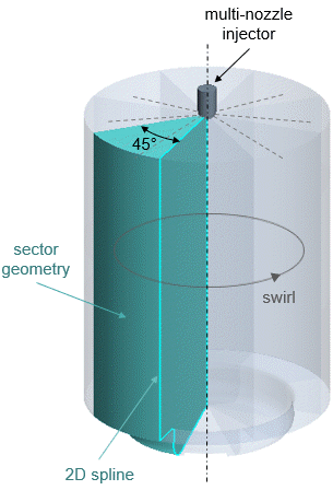
In this tutorial, you perform a closed-cycle analysis of a diesel compression-ignition engine in the interval between 680 deg CA to 800 deg CA using a 45° sector model. The geometry consists of a 2D spline that describes the profile of the cylinder sector where the piston is at BDC position:

At the center of the cylinder head, a multi-nozzle injector introduces (dodecane) into the cylinder sector. The fuel injection starts at 714.75 deg CA and ends at 722.65 deg CA. You specify the mass flow rate in tabular form as a function of crank angle. To simulate the disintegration process of the fuel jet exiting from the nozzle injector, you use the Huh Atomization model. The Reitz-Diwakar breakup model accounts for the secondary break-up of the fuel droplets after injection. To induce turbulent fuel mixing after injection, you specify an initial swirl in terms of a rotational velocity of 2000 rpm about the central axis.
The following table lists the engine characteristics and operating conditions of the diesel engine:
| Property | Value |
|---|---|
| Stroke | 158.54 mm |
| Connecting Rod Length | 270 mm |
| Speed | 1100 rpm |
You simulate the combustion process in the engine cylinder using the Extended Coherent Flame Model with Combustion Limited by Equilibrium Enthalpy (ECFM-CLEH), for which you import a library table based on complex chemistry. Automatic Composition Initialization allows you to set the initial gas composition in the cylinder using an automated approach. The combustible mixture in the engine cylinder ignites spontaneously without an external source of ignition (auto-ignition). For the computation of the ignition delay, you import a Tabulated Kinetic Ignition (TKI) table.
At the cylinder walls, you apply constant temperature conditions in the range between 400 K and 450 K. To take into account the variation of thermophysical properties in the near-wall region, you apply the Angelberger wall treatment formulation for diesel.
You run the simulation using automatic time-step control, which adjusts the time-step size based on the start and end of fuel injection.