Uniflow Two-Stroke Engine
Two-stroke engines complete the power cycle with two strokes of the piston while turning the crankshaft once (360 degrees). With Simcenter STAR-CCM+ In-cylinder, you can simulate different types of two-stroke engines—uniflow, loop flow, or cross flow engines.
In this tutorial, you perform an analysis of a uniflow two-stroke engine. For uniflow engines, the fresh air and the burned gases flow in the same direction. The fresh air enters through the intake port at the bottom of the cylinder, flows upwards, and pushes the burned gases out through the valve-controlled exhaust port at the top.
You import the geometry of the uniflow two-stroke engine with the piston in TDC position and the exhaust valve closed:
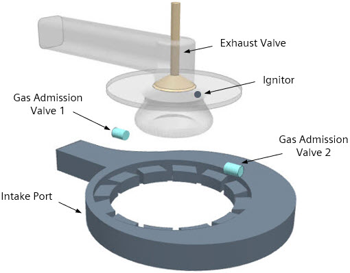
Two opposing gas admission valves (GAVs) introduce methane ( ) gas into the engine cylinder. At the inlets of the GAVs, you use tabular data to describe the mass flow rate of the methane gas as a function of crank angle. When the piston is at 10.0 deg CA before TDC, a spark ignitor starts the combustion process. To simulate the spark ignition and combustion process in the engine cylinder, you use the Extended Coherent Flame Model Three Zone (ECFM-3Z).
The following table lists the engine characteristics and operating conditions of the two-stroke engine:
| Property | Value |
|---|---|
| Stroke | 100 mm |
| Connecting Rod Length | 100 mm |
| Speed | 1000 rpm |
You represent the intake port and the GAVs with separate plenums. The opening and closing of these components are piston-controlled—sliding interfaces connect the plenums and the engine cylinder. To aid solution convergence, you refine the plenum meshes next to the interfaces using volumetric controls.
The simulation starts at 90 deg CA and ends at 450 deg CA. You run the simulation using automatic time-step control, which adjusts the time-step size based on preset valve lift thresholds, the offset between the plenums and the piston, and the ignition timing.