Defining Mesh Refinement Zones

You define mesh refinement zones on the GAVs and intake port sides of the sliding interfaces using geometries that are based on simple shape templates.

To define the mesh refinement zones:
  1. Create cylindrical geometries that contain the GAVs:
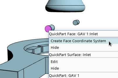
    1. In the Graphics window, right-click the inlet face of GAV 1 and select Create Face Coordinate System.
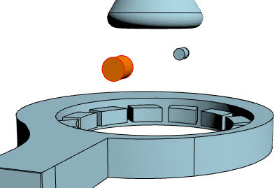

    2. In the Set Face Coordinate System Name dialog, set Coordinate System Name to GAV 1:Inlet CS, then click OK.
    3. In the object tree, right-click the Geometry node and select New Construction Geometry > Cylinder.
    4. In the Cylinder dialog, set Name to GAV 1 Volume Control.
    5. Set the following properties:
      Group Box Property Setting
      Geometry Height 12.5 mm
      Base Radius 6.0 mm
      Placement Coordinate System Laboratory > GAV 1:GAV 1: Inlet CS
      Location [X, Y, Z] [0.0, 0.0, -11.5] mm, mm, mm
      Rotation Axis Vector [X, Y, Z] [0.0, 0.0, 1.0] m, m, m
      Angle 0.0 deg
    6. Click Update, then OK.
      Simcenter STAR-CCM+ In-cylinder updates the geometry properties and the placement of the cylinder as displayed below:


    7. Repeat Steps 1 a - f for GAV 2.
      Name the new coordinate system and geometry GAV 2:Inlet CS and GAV 2 Volume Control, respectively.
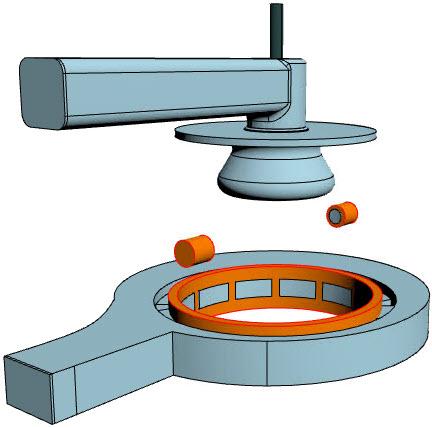
  2. Create a ring-shaped geometry that intersects with the intake port next to the sliding interface:
    1. In the object tree, right-click the Geometry node and select New Construction Geometry > Cylinder.
    2. In the Cylinder dialog, set Name to Outer Cylinder.
    3. Set the following properties:
      Group Box Property Setting
      Geometry Height 24.0 mm
      Base Radius 53.0 mm
      Placement Location [X, Y, Z] [0.0, 0.0, -105.0 mm] mm, mm, mm
    4. Click Update, then OK.
    5. Repeat Step 2 a - d to create another cylinder using the following properties:
      Group Box Property Setting
      - Name Inner Cylinder
      Geometry Height 24.0 mm
      Base Radius 48.5 mm
      Placement Location [X, Y, Z] [0.0, 0.0, -105.0 mm] mm, mm, mm
    6. Multi-select the Geometry > Outer Cylinder and Inner Cylinder nodes, right-click one of the selected nodes, and select Boolean Construction Geometry.
    7. In the Edit dialog, set Name to Intake Port Volume Control .
    8. Within the Geometry group box, set the following properties:
      Property Setting
      To Unite Outer Cylinder
      To Subtract Inner Cylinder
    9. Click Update, then OK.
    The following image displays the created mesh refinement zones:


  3. Save the simulation .