Setting Up the Injector
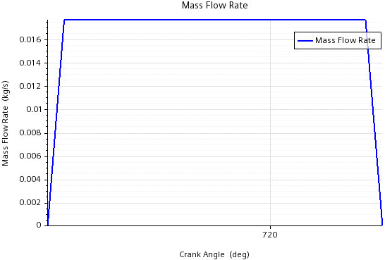
For the injection of fuel droplets into the engine cylinder, you create an injector Engine Part, which provides a template for defining the geometry and the physics of the injector. You specify the mass flow rate of the fuel in the form of a table that defines the mass flow rate as a function of crank angle. The initial temperature of the injected fuel is 310 K.
-
Right-click the Engine node and select
Create Injector.
The Edit tab opens and displays the injector template. The Graphics window updates and displays an injector with a single solid-cone nozzle. By default, the injector is centered in the cylinder head and aligned with the cylinder axis.
-
In the Graphics window, change the view to obtain a
similar engine position to the one shown below:

- Within the Edit dialog, in the Geometry tab, set the injector coordinate system to Laboratory.
The default nozzle of the injector is oriented along the x-axis
of the injector coordinate system. For a sector model, you define one nozzle per
sector.
To set up the nozzle:
-
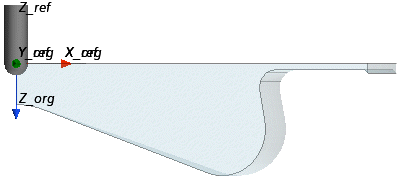
In the Nozzle Origin Reference group box, set the
following properties:
Property Setting [X, Y, Z] [1.5 mm, 0.0 m, -1.2 mm] Coordinate system Laboratory -
In the Nozzle Target Reference group box set the following
properties:
Property Setting [X, Y, Z] [2.47437 mm, 0.0 m, -1.42495 mm] Coordinate system Laboratory -
Click Update.
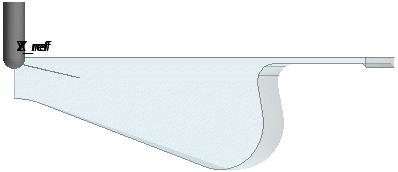
Simcenter STAR-CCM+ In-cylinder updates the position and orientation of the nozzle as displayed below:

-
In the Per Nozzle group box, set the following
properties:
Property Setting Discharge Coefficient 0.7 Diameter 0.25 mm Length 1.5 mm -
Click Update.
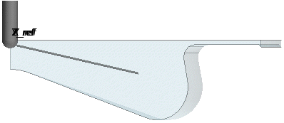
The diameter and the length of the nozzle update as displayed below:

To set up the injection conditions:
- Click the Physics tab.
-
Set the mass flow rate using tabular data:
- For Fuel Temperature, set a constant value of 310.0 K.
- Click Update, then OK.
-
Save the simulation
 .
.
