Steady Flow: Channel Flow with Multiple Meshes
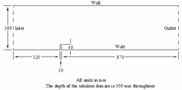
This tutorial describes a steady airflow simulation over an obstacle that is mounted at the bottom wall of a three-dimensional channel.

The case is based on an investigation from the Danish Maritime Institute, whose experimental data is compared with the Simcenter STAR-CCM+ predictions. In the experimental set-up, the flow velocity and turbulence characteristics were non-uniform across the inlet section. However, to simplify the modeling procedure, the case that is presented here is based on a parabolic inlet velocity profile with fixed turbulence characteristics.
The boundaries consist of an inlet, an outlet, a symmetry plane on one of the two ‘side’ faces and default no-slip walls. The fluid is air and its physical properties are assumed constant and equal to the Simcenter STAR-CCM+ default values.
Air enters the solution domain at standard pressure and temperature (1 bar and 293 K) with a free-stream velocity of 1.17 m/s. Based on the height of the obstacle, the Reynolds number is 3,115. The turbulence kinetic energy and dissipation rate at the inlet are set to 0.024 m2/s2 and 0.07 m2/s3, respectively, these values having been derived from experimental data. All fluid mass entering the solution domain exits through the outlet. The flow is isothermal, turbulent, and incompressible; turbulence is simulated using the standard linear k-e model that is combined with the Wolfstein two-layer model.
The same problem is modeled three times, each variant using a different mesh, as described in:
Comparisons are then drawn between the accuracy and computational speed of each type of mesh. All three meshes are based on the same initial shell surface defining the problem geometry but each was generated using a different technique.