Steady Flow: Backward Facing Step
Steady flow over a backward facing step is a typical scenario to investigate the behaviour of reattaching flows. Understanding the behaviour of the flow is crucial for many applications such as designing heat exhangers, evalutating aerodynamic performance and improving flow control strategies.
This tutorial demonstrates how to parameterize a backward facing step geometry and inflow quantities. This parameterization facilitates modification of the step height by changing just one parameter.
This tutorial simulates the turbulent gas flow across a backward facing step that is being heated along the bottom wall behind the step. You analyze the velocity magnitude across the step, the wall shear stress in the x direction and the Nusselt number. The step height is then modified to investigate the effects on the flow and heat transfer.
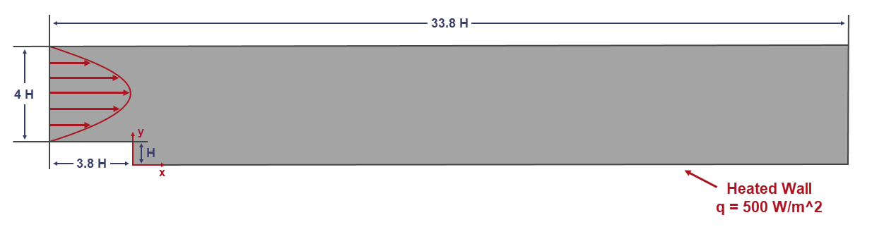
The geometry for the tutorial is created in 3D-CAD in Simcenter STAR-CCM+ in relation to the step height. You parametrize the step height of the backward facing step (represented by H in the above diagram). The geometry, turbulence specification and parabolic velocity profile at the inlet boundary are all defined in relation to the parameter. As a result, the step height can be modified without the need for other changes to the simulation set up. The K-Epsilon turbulence model with High y+ wall treatment is used as it allows you to use a relatively coarse mesh without prism layers. A custom field function is set up to model the parabolic velocity profile at the inlet boundary according to Eqn. (5243).