Polymer Melt Extrusion: Film Casting
In industry, film casting is a common process for producing thin polymeric films. Cast films are used for applications such as food and textile packaging, stretch wraps, or plastic bags. Simcenter STAR-CCM+ provides a combination of the Film Casting model and the Free Surface model that allows you to simulate that process and to investigate the impact of various parameters on the resulting film.
In the film casting process, a polymer melt is extruded through a flat slit die onto a chill roll where the melt cools rapidly. The velocity of the chill roll is higher than the velocity of the melt at the die exit. This velocity ratio, called the draw ratio, results in the polymer being stretched and being oriented in extensional flow. The material properties and the film casting process conditions have a significant influence on the film formation.
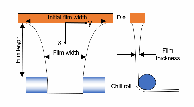
The following diagram displays a schematic film casting process:

- Initial film width: 0.2 m
- Film thickness at the die exit: 0.46 mm
- Film length—distance between the die exit and the point of contact between the film and the chill roll: 0.23 m
- Draw ratio—defined as the ratio of the film velocity at the chill roll to the velocity at the die exit:(5247)
This tutorial demonstrates how to model a film casting extrusion of a polymer melt in Simcenter STAR-CCM+. The geometry and the mesh that you create model only the film itself. The die and the chill roll are not accounted for geometrically, but their influence is applied as boundary conditions. The computational mesh is two-dimensional and describes the width and the length of the film. The mesh is initially of rectangular shape with the width being the initial film width. The variation in film width along the extrusion direction is calculated by the Free Surface model. In the course of the steady-state simulation, the mesh deforms by use of the morpher according to the predicted film width. The film thickness is not resolved by the mesh, but is computed as a scalar quantity by the Film Casting model—you analyze its distribution on the two-dimensional mesh. As the process configuration is symmetric about the centerline you only need model half the geometry.