Creating the Initial Film Mesh
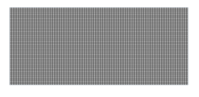
In Simcenter STAR-CCM+, a two-dimensional mesh is required for simulations of film casting. The mesh that you create represents the initial undeformed state of the film. In the course of the simulation the mesh deforms as part of the solution.
To create the 2D mesh, you apply the directed mesher to the block surface that lies on the Z = 0 plane.
To create the initial film mesh:- Right-click the node and select New Geometry Part.
- In the Part Creation Options dialog, accept the default settings and click OK.
- Create a geometry scene.
- To provide separate surfaces on which to define boundary conditions, right-click the node and select Split by Angle, then click OK.
-
Identify the part surface that lies on the X-Y plane at Z = 0, onto which you create the 2D mesh:
- Right-click the Operations node and select .
- In the Create Badge for 2D Meshing Operation dialog, select Body 1 and activate Execute upon Creation, then click OK.
-
Assign the badged body and its surfaces to a region with boundaries:
- Right-click the node and select Assign Parts to Regions.
- In the Assign Parts to Regions dialog, leave Create One Region for All Parts, but rename Region as Film.
- Select Create a Boundary for Each Part Surface.
- Click Apply, then Close.
-
Create a two-dimensional directed mesh consisting of quadrilateral cells:
- Right-click the Operations node and select .
- In the Create Directed Mesh Operation dialog, select Body 1, then click OK.
- Right-click the node and select Edit.
- In the Directed Mesh simulation tree, select the Source Surfaces node and set Source Surfaces to Default 5.
- Select the Target Surfaces node and set Target Surfaces to Default 6.
- Right-click the Source Meshes node and select .
- In the Part Collection For This Source Mesh dialog, select Body 1, then click OK.
-
In the
Patch Topology panel, click
 (Auto-populate feature edges with patch curves).
- To specify the cell distribution along the edges of the 2D directed mesh, set Mode to Patch Mesh.
- In the Graphics window, select one of the short edges, set Number of Divisions to 60, then click Apply.
- Then, select one of the long edges, set Number of Divisions to 100, and click Apply.
- Click Close.
- Right-click Mesh Distributions and select New Volume Distribution.
- In the Parts for creating a new mesh distribution dialog, select Body 1, then click OK.
- Click Close Directed Mesh.
- Right-click the node and select Execute.
-
Create a mesh scene.

- Save the simulation.