Within 3D-CAD, you create the geometry of the film in its undeformed state and then apply design parameters to its length and width. Thereafter, in the simulation setup, you create global parameters for use when defining process conditions at boundaries.
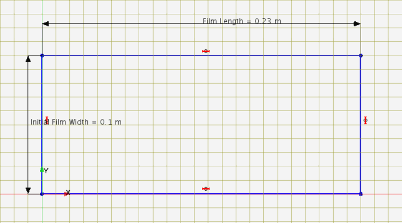
The geometry you create is a rectangle whose width corresponds to half the initial width of the film, (hence 0.1 m), and whose length is that of the film length, 0.23 m. You specifically create the rectangular sketch on the X-Y plane and extrude it in the Z direction so that later you can create a 2D mesh on the X-Y plane at Z = 0.
You define global parameters for the velocity and thickness of the film as it enters the simulation—the die exit velocity and die film thickness respectively. You also define a parameter for the film draw ratio.
To define and parametrize the geometry:
-
Launch a double precision version of
Simcenter STAR-CCM+ and start a new simulation.
-
Create the geometry that defines the undeformed film:
-
Right-click the
node and select
New.
-
In the
3D-CAD panel, right-click
and select
Create Sketch.
-
In the
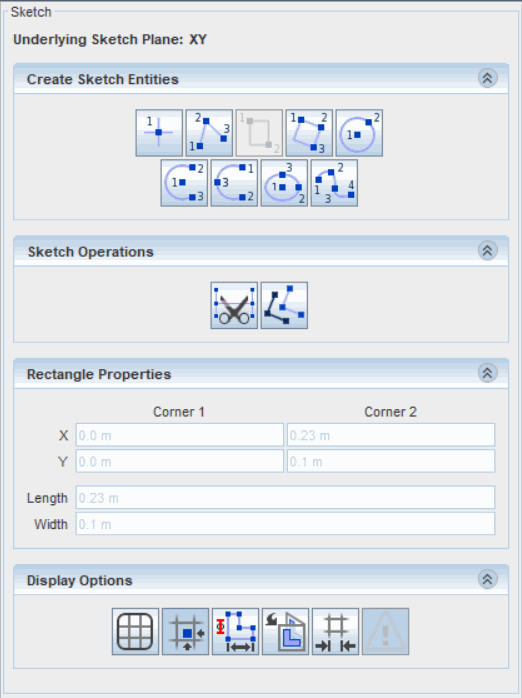
Create Sketch Entities group box, click
 (Create Rectangle).
-
In the
Graphics window, create a rectangle on the sketch plane with the first corner on the origin, position [0 m, 0 m] and the second corner at position [0.23 m, 0.1 m] ending up with a
Width of 0.1 m and a
Length of 0.23 m.
-
Define the initial film width and the film length as design parameters:
-
Right-click one of the vertical lines and select
Apply Length Dimension.
-
In the
Dimension dialog, activate
Expose Parameter, enter
Name as
Initial Film Width, then click
OK.
-
Right-click one of the horizontal lines and select
Apply Length Dimension.
-
In the
Dimension dialog, activate
Expose Parameter and enter
Name as
Film Length, then click
OK.
-
Click
OK to close the
Sketch panel.
-
In the
3D-CAD simulation tree, expand
to review the design parameters.
-
Extrude the sketch:
-
Right-click the
node and select
Extrude.
-
In the
Extrude panel, accept all default settings and click
OK.
-
Click
Close 3D-CAD.
Continue by defining global parameters that characterize the film entry conditions and draw ratio.
-
To define the global parameters:
-
In the Simcenter STAR-CCM+ simulation,
right-click the node and select .
-
Rename the
node as
Die Exit Velocity and set the following properties:
| Property
|
Setting
|
| Value
|
[0.0043, 0.0, 0.0]
|
| Dimensions
|
Length/Time (In the
Dimensions dialog, set
Length = 1 and
Time = -1.)
|
-
Create another parameter, a scalar parameter, and rename it as
Die Exit Film Thickness.
-
Select the
Die Exit Film Thickness node and set the following properties:
| Property
|
Setting
|
| Value
|
4.6E-4
|
| Dimensions
|
Length
|
-
Create another scalar parameter and rename it as
Draw Ratio.
-
Select the
Draw Ratio node and set
Value to
15.
-
Save the simulation as
filmCasting.sim.
 (
(
