Creating the Backward Facing Step Geometry
You define the geometry for the backward facing step in relation to a set parameter for the step height. This approach allows for easy scaling of the model later.
-
Create a new simulation:
- Start up Simcenter STAR-CCM+ in a manner that is appropriate to your working environment and create a new simulation.
- Save the new simulation with the file name backwardFacingStep.sim
-
Create a parameter for the step height to use when creating the geometry:
-
Create a 3D-CAD model:
- Right-click the node and select .
- Select the node and rename it to Fluid Domain.
-
Create the geometry of the backward facing step:
-
In Display Options, click
 (Set Sketch Grid
Spacing) and change Grid
Spacing to 0.25 m.
(Set Sketch Grid
Spacing) and change Grid
Spacing to 0.25 m.
-
In Display Options, click
 (View Normal to Sketch
Plane) to bring the sketch plane into view.
(View Normal to Sketch
Plane) to bring the sketch plane into view.
-
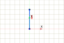
In Create Sketch Entities, click
 (Create Line) to
draw a line of length 1.0 m, starting at the
origin (position [0, 0]) and extending in the
positive y direction. After placing the end point, click
[esc] to end the line.
(Create Line) to
draw a line of length 1.0 m, starting at the
origin (position [0, 0]) and extending in the
positive y direction. After placing the end point, click
[esc] to end the line.
-
In Display Options, click
-
Apply constraints to the line:
-
Draw the other lines in relation to the step height:
-
Using the same techniques, continue by creating the other lines, each
in relation to the parameter $StepHeight, which
corresponds to the step height H in the diagram below:
-
Using the same techniques, continue by creating the other lines, each
in relation to the parameter $StepHeight, which
corresponds to the step height H in the diagram below:
-
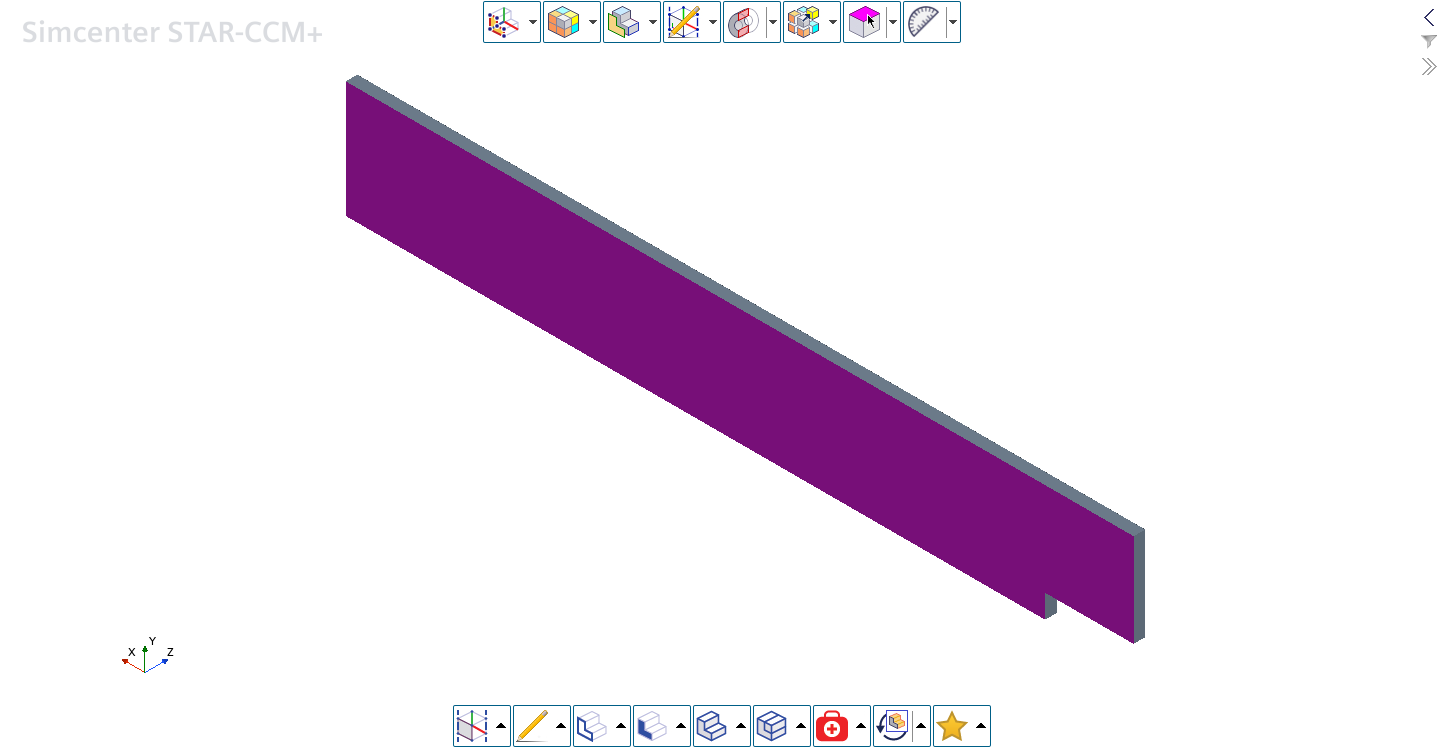
Extrude the sketch profile to obtain a solid body:
-
Rename the geometry faces:
-
Click
 in the toolbar and select .
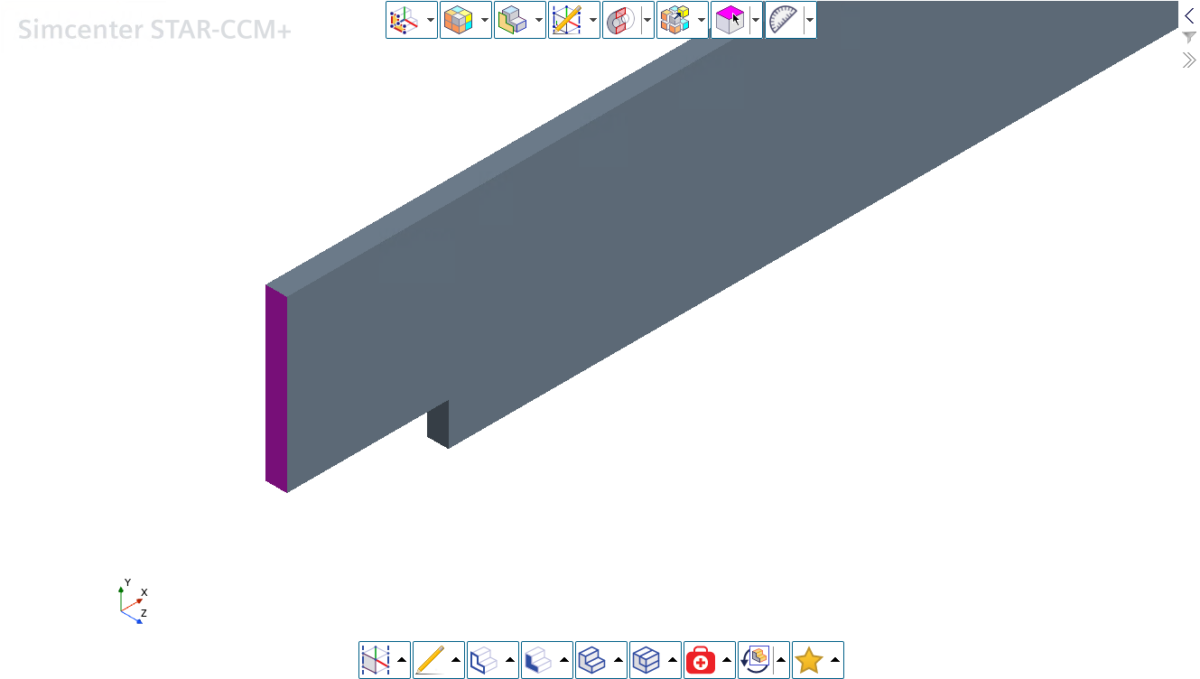
-
Right-click the face shown below and select
Rename. Rename the face to
Inlet and click
OK.
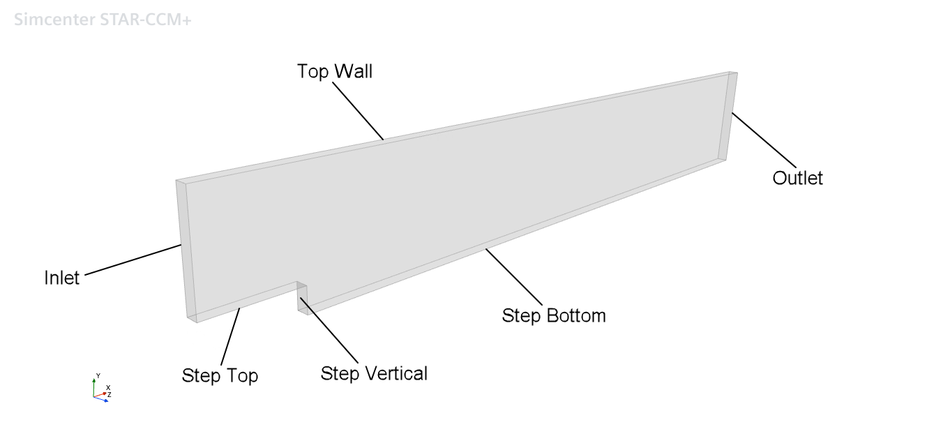
-
Rename the other faces in the geometry to match those shown
below:
-
Click in the toolbar and select .
-
Rename the surface that lies on the Z = 0 plane to Surface
for 2D Mesh, as shown below:
This surface is used at a later stage to generate a 2D mesh.
-
Click
-
Create the shape to use as a volumetric refinement area:
-
Click
 (Create Rectangle)
and draw a rough box around the bottom half of the geometry so that it
covers the step, as shown below:
(Create Rectangle)
and draw a rough box around the bottom half of the geometry so that it
covers the step, as shown below:

-
Click
-
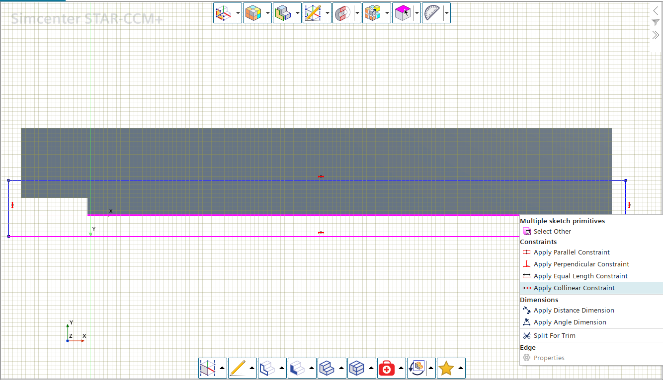
Constrain the sketch so that the left, right and bottom edges are collinear
with the corresponding edges of the backward facing step geometry:
-
Select the bottom edge of the rectangle and the bottom edge of the
solid part, then right-click the selection and select Apply
Collinear Constraint.
-
Select the bottom edge of the rectangle and the bottom edge of the
solid part, then right-click the selection and select Apply
Collinear Constraint.
-
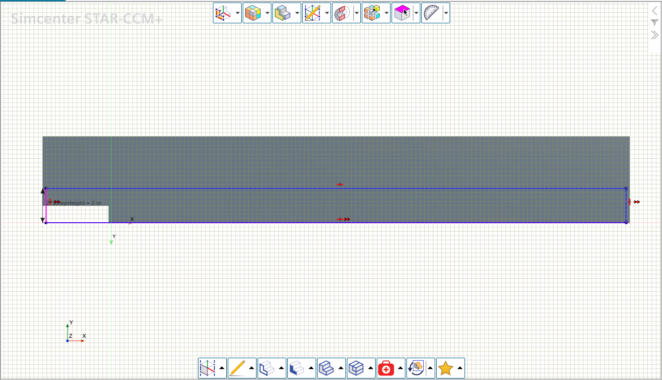
Add a dimension for the height of the box, so that its height is twice the step
height:
-
In the Dimension dialog, enter
2 * $StepHeight and click
OK.
-
In the Dimension dialog, enter
2 * $StepHeight and click
OK.
- Click OK to exit Sketch Mode.
-
Create a solid body from the sketch:
-
Select the surface opposite the sketch plane.
A preview of the box appears, and the Target Face property in the panel shows the name of the surface.

-
Select the surface opposite the sketch plane.
-
Create a new geometry part using the 3D-CAD model:
- Right-click the node and select New Geometry Part.
- In the Parts Creation Options dialog, the default settings are acceptable so click OK to close the dialog.
- Expand the node to see the boundary faces specified in 3D-CAD as separate faces.
- Save the simulation.