Setting Up Shell Region and Boundary Conditions
Create a shell region and define the boundary conditions.
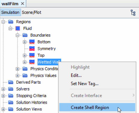
In this tutorial liquid film forms on the Wetted Wall boundary of the Fluid region. A shell region is required for all boundaries on which fluid film is to flow. This shell region is created from the Wetted Wall boundary.
To create a shell region and define the boundary conditions:
-
Right-click the
node and select
Create Shell Region.

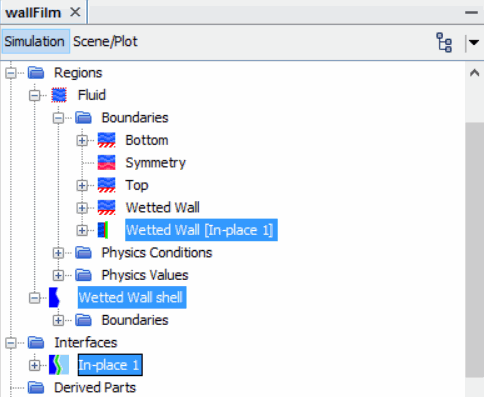
A new shell region is added to the simulation tree. In addition, an interface is formed between the fluid region and the shell region, which is based on the geometry of the Wetted Wall boundary surface. The original boundary therefore becomes an interface to the film shell region.

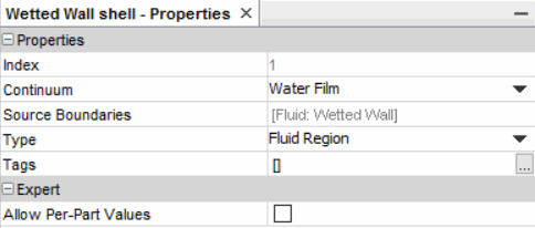
The water film phase must be assigned to the Wetted Wall Shell region.
-
Select the
node and set the
Continuum to
Water Film.

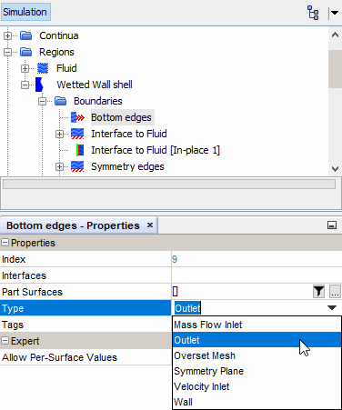
Specify the actual fluid film boundary conditions using the nodes within the Wetted Wall Shell region. These boundaries are formed from the edges of the original Wetted Wall boundary from which the shell region was created. By default all boundaries are set to no-slip wall, except the Interface to Fluid [In-place 1], which is set to the Fluid-Film Boundary type. So that the fluid film can leave the domain, you change the boundary type of the Bottom edges boundary. Set the type for this boundary to Outlet.
-
Select the
node and set
Type to
Outlet.

- Save the simulation.