Marine Resistance Prediction: KCS Hull with a Rudder
This tutorial demonstrates the workflow for setting up a resistance prediction simulation for a marine application.
The geometry that is used is the [980]. This geometry was used as part of a series of simulations that were performed for the Gothenburg Workshop 2010 on Numerical Ship Hydrodynamics. The STAR-CCM+ simulation results were compared with experimental towing tank data.

The simulation is performed in model scale. The hull length is approximately 7.7 m (length between perpendiculars Lpp= 7.2786 m) with a scale factor of 31.6. The coordinate origin is at aft perpendicular and still water surface. The still water surface is at 0.341772 m above keel.
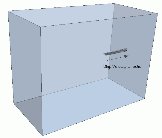
Only half of the geometry is modeled due to symmetry conditions. The computational domain extends from:
- -18 m to 18 m in the flow direction
- -18 m to 9 m in the vertical direction
- 0 m to 18 m in the lateral direction
The following boundary conditions are applied:
- Symmetry plane at the hull midplane
- Symmetry plane at the side of the tank
- Hydrostatic pressure corresponding to the undisturbed water surface at the downstream boundary of the tank
- Inlets with prescribed velocity and volume fraction at the upstream, top, and bottom boundaries.
To obtain resistance data experimentally, the ship hull is towed through the towing tank. For the equivalent simulation, the ship remains in a fixed position, and an inlet velocity is prescribed at the upstream inlet boundary. This inlet velocity produces the relative movement. The ship is free to heave and pitch. The simulation starts from a flat water surface with the bottom of the hull being parallel to the free surface. The computation is performed for a Froude number of Fn = 0.2599.
You can work through the tutorial in three major steps: