Mesh: Refining the Mesh
Customize and refine specific areas of the simulation domain using custom controls.
Custom controls override the default controls for the areas that you specify. For example, you can customize the number of prism layers that are generated on a surface that is specified within a custom control. The number of prism layers that are generated outside the custom control match the settings in the default controls.
Local meshing speeds up the re-execution of the surface remesher after local changes are made to the input geometry or mesh settings. With this feature, Simcenter STAR-CCM+ only remeshes surfaces within a defined location and leaves other surfaces unchanged. With local meshing, you set limits on where you want remeshing to occur by defining local extents. In this tutorial, the area surround the fan contains all the changes and refinements to the mesh, so it would be ideal to use a volume extent that encloses the fan.
Create custom controls that focus on specific areas of the simulation domain:
-
Launch Simcenter STAR-CCM+ and load foundationTutorial_10.sim.
You can either use the sim file that you saved from the previous tutorial, or load the sim file provided in the tutorials bundle. See Downloading the Tutorial Files from the Support Center Portal.
- Save the simulation as foundationTutorial_11.sim.
- If the scene showing the fan and enclosure is not open, double-click the node.
-
Adjust the prism layer settings to improve the quality of the prism layer cells around the fan blades and in the small gap between the base of the fan and the enclosure:
-
Set up local meshing:
The changes made in the previous step improve the prism layers, however further refinement is still required in the rotating region. Local meshing limits the changes to the specified extent, reducing the total time it takes to generate the surface mesh. Areas outside the extent remain unchanged.
-
Create a custom control that disables the generation of prism layers on the interface between the static region and the rotating region:
Prism layers are not required at this location so you can disable them to reduce the cell count in the mesh.
-
Select the Disable Prism Layer node and click
 (Custom Editor) next to Part Surfaces.
-
Select the Disable Prism Layer node and click
-
Create a custom control that refines the cell size in the rotating region and customizes the prism layer around the fan blades:
The rotating graphics card fan contains narrow gaps and would benefit from a finer mesh to capture the flow in and around the fan more accurately. The prism layer is especially important around the fan blades, where the swirling flow is generated. The current prism layer is too thick to resolve the boundary layer accurately, and the prism layer cells are too large. To improve the mesh, decrease the prism layer total thickness.
-
Select the Fan Cell Refinement node and click (Custom Editor) next to Parts.
-
Select the Fan Cell Refinement node and click
- Save the simulation.
-
To update the volume mesh with the changes, right-click the Automated Mesh node and select Execute.
The mesh generation takes less time as only the surface mesh inside the extent are regenerated. Surfaces outside the extent remain unchanged and do not mesh. If you want to modify an area outside the extent, either add another extent to cover this area or if more general changes are required, disable local meshing.
- To update the surface and volume extruder, right-click the Operations node and select Execute All.
-
View the mesh quality scenes:
-
Select the Mesh View: XY tab in the window.
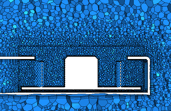
The refined cells inside the rotating region are clearly visible. The prism layer thickness inside the rotating region shrinks to fit inside the tight spaces. The prism layer is no longer collapsed in the small gap below the fan.
-
Select the Mesh View: XZ tab in the window.

The refined cells inside the rotating region are clearly visible. The prism layer is no longer generated between the two regions. The prism layer is no longer collapsed at the tips of the fan blades.
-
Select the Mesh View: XY tab in the window.