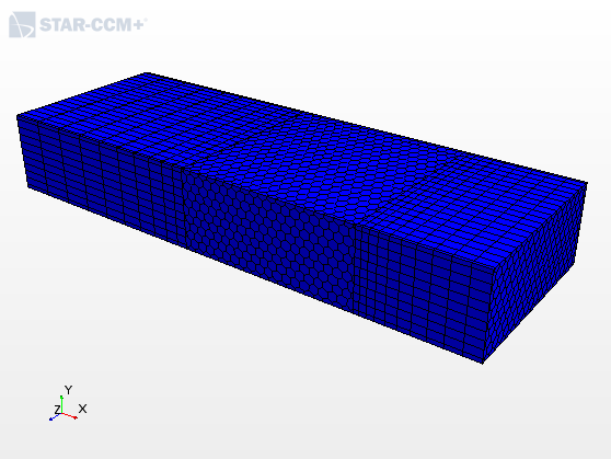
Mesh: Extending the Simulation Domain with the Mesh Extruder

Cell count is important due to computational costs. Larger meshes increase computational time for the solver. One way of keeping the cell count down, while at the same time extending the simulation domain, especially on the inflow and outflow boundaries, is to use the extruder mesher.

The extruder mesher is made up of two operations: the surface extruder, and the volume extruder. The surface extruder extends the edges of the input surface to form the bounding surfaces of the extruded region. You specify the extrusion distance in the surface extruder operation. The volume extruder fills in the extruded region with extruded volume cells from the input surface. You control the amount of divisions in the extruded region in the volume extruder operation.

  1. Launch Simcenter STAR-CCM+ and load foundationTutorial_9.sim.

    You can either use the sim file that you saved from the previous tutorial, or load the sim file provided in the tutorials bundle. See Downloading the Tutorial Files from the Support Center Portal.

  2. Save the simulation as foundationTutorial_10.sim.
  3. If the scene showing the simulation domain is not open, double-click the Scenes > Simulation Domain node.
  4. Create the Surface Extruder operation for the upstream region:
    1. Right-click the Geometry > Operations node and select New > Surface Preparation > Surface Extruder.
    2. In the Create Surface Extruder Operation dialog, click Select next to the Input Parts field, select Static Region and click OK.
    3. Click Select next to the Input Part Surfaces field, select Static Region > Block > Upstream and click OK.
    4. Set Extrusion Distance to 0.25 m.
    5. Click OK to close the Create Surface Extruder Operation dialog.
      A surface extruder operation is added to the Operations node, and a placeholder for the surface extruder part is added to the Parts node.
    6. Rename the Parts > Surface Extruder node to Upstream Region.
    7. Rename the Operations > Surface Extruder node to Upstream Surface Extruder.
  5. Create the Surface Extruder for the downstream region:
    1. Click and drag the Operations > Upstream Surface Extruder node onto the Operations node.
      A copy of the surface extrude operation is created and added to the Operation node and a copy of the surface extruder part is added to the Parts node.
    2. Rename the Parts > Upstream Surface Extruder copy node to Downstream Region.
    3. Rename the Operations > Upstream Surface Extruder copy node to Downstream Surface Extruder.
    4. Select the Operations > Downstream Surface Extruder node and switch the Input Part Surfaces to Static Region > Block > Downstream.
    5. Select the Downtream Surface Extruder > Controls > Direction Mode > Extrusion Distance node and set Extrusion Distance to 0.5 m.
  6. Create the Volume Extruder operation:
    1. Right-click the Operations node and select New > Mesh > Volume Extruder.
    2. In the Create Volume Extruder Operation dialog, select Downstream Region and Upstream Region and click OK.
      A volume extruder operation is added to the Operations node.
    3. Select the Volume Extruder > Controls > Number of Layers node and set Number of Layers to 10.
    4. Select the Volume Extruder > Controls > Stretching Function node and set Stretching Method to One Sided Hyperbolic.
  7. Assign the extruded parts to regions:
    1. In the Geometry > Parts node, select the Upstream Region and Downstream Region nodes.
    2. Right-click on a selection and choose Assign Parts to Regions....
    3. In the Assign Parts to Regions dialog, select:
      1. Create a Region for Each Part
      2. Create a Boundary for Each Part Surface
      3. Create Contact-mode Interfaces From Contacts
      4. Click Apply then Close.
    4. Expand the Regions > Downstream Region > Boundaries node, select the Block.Downstream and Static Region.Block.Block Surface boundaries, and set Type to Symmetry Plane.
    5. Expand the Regions > Upstream Region > Boundaries node, select the Block.Upstream and Static Region.Block.Block Surface boundaries, and set Type to Symmetry Plane.
  8. Right-click the Operations node and select Execute All.
  9. Add the new regions to the mesh scene showing the simulation domain:
    1. In the Regions node, multi-select the Downstream Region and Upstream Region regions.
    2. Click and drag these regions into the Simulation Domain scene and select Existing Displayers > Mesh 1.


  10. Save the simulation.