Prepare the regions for the simulation domain and select the meshers.
Begin by creating the regions:
-
Launch
Simcenter STAR-CCM+ and load
foundationTutorial_7.sim.
-
Save the simulation as
foundationTutorial_8.sim.
-
Create the regions from the geometry parts:
-
If the geometry scene is not open, double-click the
node.
-
Expand the
node.
-
Select the
Rotating Region and
Static Region nodes.
-
Right-click on a selection and choose
Assign Parts to Regions....
-
In the
Assign Parts to Regions dialog, select:
- Create a Region for Each Part
- Create a Boundary for Each Part Surface
- Create Contact-mode Interfaces From Contacts
- Click
Apply then
Close.
The geometry in the scene changes to a dark gray color to show that parts displayed in the scene are assigned to regions. Parts that have no region association are displayed in a light gray color.
-
Create an automated mesh operation and select the mesh models:
-
Right-click the
node and select
.
-
In the
Create Automated Mesh Operation dialog:
- Select
Rotating Region and
Static Regon from the
Parts list.
- Select the following meshers, in order:
| Group
|
Mesher
|
| Surface Meshers
|
Surface Remesher
|
| Core Volume Meshers
|
Polyhedral Mesher
|
| Optional Boundary Layer Meshers
|
Prism Layer Mesher
|
The Surface Remesher retriangulates the surface of the geometry and improves the overall quality of the initial surface. The Polyhedral Mesher generates polyhedral cells that are suitable for turbulent and swirling flow simulations. The Prism Layer Mesher generates a prism layer (orthogonal prismatic cells) next to wall surfaces or boundaries. Prism layer cells are important for resolving the boundary layer and the velocity gradient of the flow near surface.
-
Click
OK.
An automated mesh operation,
Automated Mesh, is added to the
Operations node. The mesh models that you select are located inside this operation under the
Meshers node.
-
Set up the mesh parameters:
-
Expand the
node.
The global mesh parameters are located under this node.
-
Select
Base Size and set
Value to
2 mm.
The base size is the reference length for all reference size controls. Using the value that you specify in the base size, you can scale the mesh using relative size controls as a percentage of the base size, or set these controls independently using absolute values. Typically you set the base size to the scale of the object of interest, in this tutorial this is the fan blades in the graphics card.
-
Select the
Target Surface Size node, select
Relative to Base and set
Percentage of Base to
1000 in the Properties Window.
The target surface size is set as a percentage of the base size and specifies the cell size that the meshers should aim for when generating the mesh. The target size can be smaller or larger than the base size, and you can use it to grow or shrink the cells in the mesh.
-
Select the
Minimum Surface Size node, select
Relative to Base and set
Percentage of Base to
50 in the Properties Window.
The minimum surface size specifies the smallest element size that the mesher can generate. The thickness of the fan blade is 1 mm, while the base size is 2 mm. Setting the minimum surface size to 50% of the base size returns 1 mm and allows the mesh to capture the details of the fan blades.
-
Select the node, set Size Type to
Absolute, and set Absolute
Size to 2 mm in the Properties Window.
By default, all size controls are set as a percentage of
the base size. By setting the size type to absolute, you make this
property independent of the base size. Absolute values are useful when
you want to have full control over the size of a particular setting.
Boundaries in the simulation regions affect how the mesh is generated. More specifically, prism layers are generated next to wall boundaries and interfaces (the contacting surface between the regions). The far field walls of the simulation domain (the walls that are far away from the object of interest) are not important for this simulation; however, for the purpose of this tutorial, the size of the simulation domain is smaller than what is recommended for industrial cases. Ideally the far field surfaces in the simulation domain should be further away, as having these surfaces close to the geometry of interest will affect the flow inside the simulation domain. One way to reduce the effect of the walls on the overall flow inside the simulation domain is to set the outer surfaces to symmetry boundaries. Prism layers are not generated on symmetry boundaries.
-
Set the walls of the simulation domain to symmetry boundaries:
-
Expand the
node.
-
Select the
Block.Block Surface,
Block.Downstream, and
Block.Upstream nodes and set
Type to
Symmetry Plane.
The selected boundary surfaces change to a blue color in the geometry scene to indicate that they are symmetry boundaries.
-
Save the simulation.
-
To generate the volume mesh, right-click the
Automated Mesh node and select
Execute.
The surface remesher retriangulates the initial geometry surface tessellation into more evenly sized triangles. The space for the prism layer is calculated and reserved, this is called the prism layer subsurface. The polyhedral mesher creates three-dimensional cells, called tetrahedra, from the retriangulated surface and converts them to polyhedra. The prism layer is then generated and fills the reserved space with prism layer cells.
-
Create a mesh scene to visualize the mesh:
-
Right-click Scenes and select .
-
Rename the
node to
Simulation Domain.
-
Create another mesh scene and rename it to
Fan and Enclosure.
-
Click
Scene/Plot above the simulation object tree.
-
Double-click the node.
-
In the
Parts dialog, right-click on a blank area of the dialog and select
Deselect All to clear the selection.
-
In the same dialog, expand the
Regions node.
-
Select the
and
.
-
Click
OK.
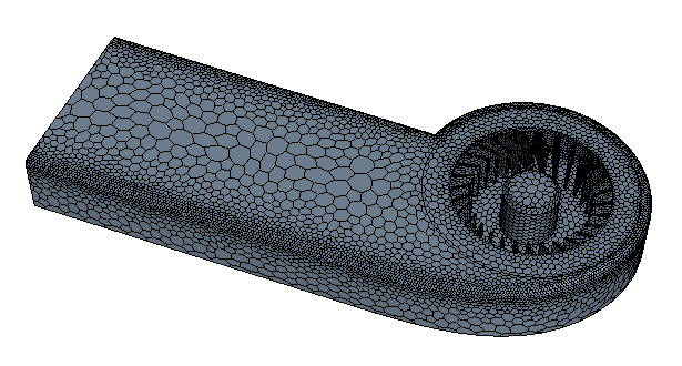
The cell size automatically adjusts, within the specified parameters, to capture the shape of geometry.
-
Save the simulation.