Preparing a Scene for Advanced Rendering
Set up two identical scenes to compare the effects of advanced rendering.
Rendering a photorealistic scene requires the use of several materials to represent the different components on the model. Every material has its own unique material properties. To capture these properties in Simcenter STAR-CCM+, you require a separate displayer for each material that you want to model. An overview of the materials used on the car is shown below. Parts that are contained in the same displayer (same color in the diagram) are rendered using the same material properties. You can set specific attributes and properties for each material.
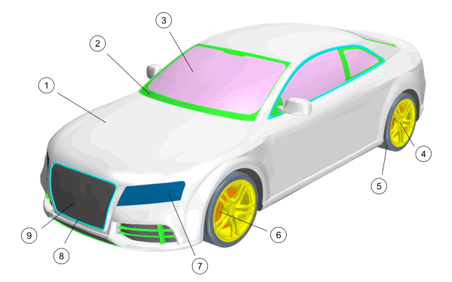
| Index | Description | Material Appearance |
|---|---|---|
| 1 | Car Body | White (Gloss) |
| 2 | Plastic Trim | Black (Gloss) |
| 3 | Simulation Data (Windscreen, Side Windows, Wing Mirrors) | Static Pressure Field Function |
| 4 | Wheels | Silver (Metal) |
| 5 | Tires | Dark Rubber |
| 6 | Brake Rotors | Gray (Matte) |
| 7 | Headlamp Lens | Gray (Transparent) |
| 8 | Chrome Trim | Silver (Metal) |
| 9 | Underbody and Air Intakes | Black (Matte) |
Open the provided scene and set it up for advanced rendering:
-
Open the
scene.
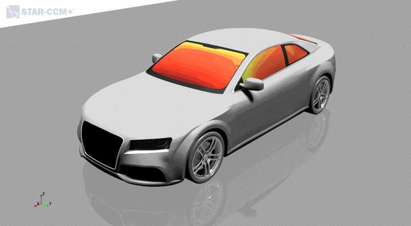
The scene starts to render. The estimate time to completion is displayed on the top-right corner of the scene. If you are planning on making a lot of changes to the scene, and advanced rendering is turned on, the scene would update and render every time after each change. You can either choose to deactivate advanced rendering or reduce the quality of the rendering.
- Click the Scene/Plot tab.
- Select and set Quality to 0.1.
- Expand the node and set the Intensity property of Light 1 and Light 2 to 0.7.
-
Change the color map of the scalars and streamlines:
- Expand the Static Pressure Windows, Streamlines: Wing Mirror, and Streamlines: Underbody displayer nodes.
- Multi-select the Color Bar sub-nodes of the displayers.
- Set Color Map to blue-red balanced.
-
Create a displayer to contain the ground:
-
Define the color properties for the ground:
-
Select the
node and click
 (Custom Editor) next to the color.
-
Select the
node and click
-
Set up the advanced rendering properties for the ground:
-
Set
Reflection to
0.3.
Reflection specifies how much of the light bounces off the material. The range is 0 to 1. A value of 0 makes the material have a matte appearance, and a value of 1 makes the material reflect all the light. The ground now reflects the objects that lie on top of it.
-
Select the
node and activate the
Enable Shadows option.
This option enables shadows to be cast on the ground surface. The shadows from the car are cast onto the ground. You can control which surfaces receive shadows locally for each individual displayer, or you can control the shadows at a global level from the Advanced Rendering Properties node at the bottom of the object tree for the scene.
-
Set
Reflection to
0.3.
-
Define the material for the tires:
-
Display the remaining simulation data in the scene:
-
In the Advanced Rendering On node, multi-select
the Streamlines: Underbody and
Streamlines: Wing Mirror nodes, right-click
and choose Toggle Visibility.
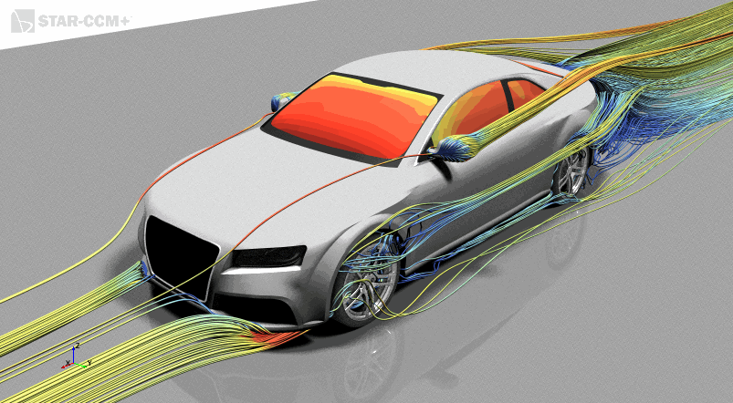
The displayers are activated and the simulation data is loaded into the scene. The streamlines can take a few minutes to calculate before they appear in the scene.
-
Select the
node and activate the
Casts Effects option.
This option causes the parts in the specified displayer to cast their effects onto other materials.
In the following example, the view is zoomed into the front wheel to see the effects that the streamlines have on the other materials in the scene. With Casts Effects deactivated, the streamlines have no effect on the other materials in the scene.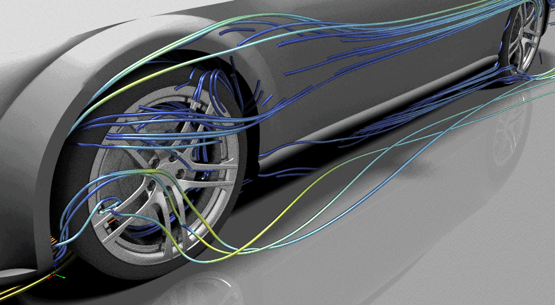
Activating the Casts Effects option causes the streamlines to appear in the reflection on the wheels, the car body, and the ground.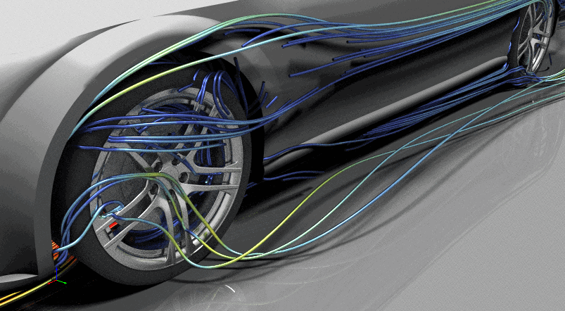
-
In the Advanced Rendering On node, multi-select
the Streamlines: Underbody and
Streamlines: Wing Mirror nodes, right-click
and choose Toggle Visibility.
- Now that the scene is set up fully, select and set Quality to 0.25.
- Save the simulation.