Extracting Fluid Volumes
Follow these steps to define air and coolant domains for an electronics cooling simulation.
Simcenter STAR-CCM+ allows you to model internal flow, external flow, or both.
- For internal air or coolant flow, you extract the void between the components that enclose the relevant domain.
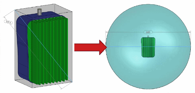
- For external flow, you must first create a shape to let the fluid move around the electronics device. Typically, you use a sphere or hemisphere whose outer surface represents the far-field conditions of the flow. Make the diameter of the sphere or hemisphere three to five times the length of the longest diagonal of the model.

If the device is mounted on a wall, table, or ceiling, you define a hemisphere.
For an external fluid domain, you create a suitable Construction Geometry that describes the volume of interest. For an internal fluid domain, you can use a combination of QuickParts and a Construction Geometry to define the volume of interest.
-
If necessary, create the appropriate Construction Geometry using one of the following methods:
Geometry of External Air Domain Procedure Sphere Create a Sphere Construction Geometry. See Creating Construction Geometries. Hemisphere Create a sphere and a block geometry—where one block plane cuts through the center of the sphere—and subtract the block from the sphere: - Create a Sphere Construction Geometry and a Block Construction Geometry. See Creating Construction Geometries.
- Right-click the node and select Boolean Construction Object.
- Within the in-place dialog, in the Geometry section, set To Subtract to the created Block Construction Geometry.
- Click OK.
-
Right-click the
QuickParts node and select
Create Extract Volume.
The Extract Volume in-place dialog appears.
-
Within the
Geometry section, in the
Extract Volume Domain Defined By group box, activate the appropriate option:
- Construction Geometry
Use the selected construction geometry to create a fluid analysis domain. You use this option to set up and extract an external fluid domain.
- QuickParts and/or Construction Geometry
Use the selected QuickParts and (optionally) the selected construction geometry to create a fluid analysis domain. You use this option to extract an internal volume of an electronics device.
- Construction Geometry
Select the objects that enclose the volume of interest. The union of all the components of the selected construction geometry and the selected QuickParts defines the boundary of the volume that is extracted.
-
Click the
Construction Geometry or
QuickParts and/or Construction Geometry box (whichever is appropriate) and do the following:
- For an internal air domain, select the QuickParts that enclose the air, such as an Enclosure QuickPart.
- For a coolant domain, select the Generic QuickParts and the construction geometry that represent the tubes of the cooling loop.
-
For open enclosures or cooling loops that contain entry and exit holes, set the
Inlet/Outlet Edges or Faces (applies to
QuickParts and/or Construction Geometry only):
-
Within the
Physics section, set the material of the extracted volume:
- For an internal air domain, select Gas.
- For a coolant domain, select Liquid.
-
Click
OK and
Return.
An Extract Volume QuickPart appears in the tree.