Visualizing the Initial Surface
Visualize the initial surface of the geometry.
In this example, all surfaces are contained within a single part, trainAndTrack. During the initial model preparation, the surface was divided into separate surfaces and these were given appropriate names.
-
Click
 (Make Scene Transparent).
- Expand the node.
-
Select the
TrainEngine node.
The TrainEngine surface is highlighted on the model.
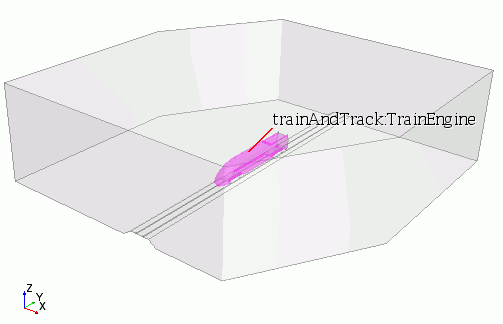
- Select each of the surfaces and observe which part is highlighted.
Remove two of the surfaces from the current scene to view the mesh on the internal features.
- Edit the node.
- In the Parts dialog, expand the Surfaces nodes and deactivate the Inflow and Top surfaces.
- Click OK.
It is possible to toggle the visibility of any displayer in a scene to disable a particular displayer without deleting it from a scene.
-
Right-click the
Outline 1 node and select
Toggle Visibility.
The outline is no longer displayed in the scene.
-
In the
Vis toolbar, click
 (Show All Meshes) to display the mesh.
-
In the
Vis toolbar, click
(Make Scene Transparent) to restore the scene transparency.
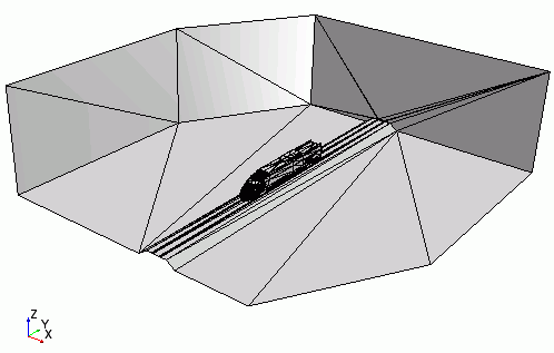
This type of mesh is generated when neutral format data or native CAD data is imported into Simcenter STAR-CCM+, and is known as a tessellated surface mesh.