Guidelines for Simulating Air Flow in Electronic Systems
This section describes guidelines for simulating heating and air flow in electronics systems.
These guidelines are an iterative process, using the following steps, repeated until a satisfactory result is obtained:
- Preparing and refining the geometry:
Start with a model in 3D-CAD or a similar CAD modeler, consisting of composite parts and regions. Simplify this and define the interfaces.
- Preparing and refining the mesh:
Use pre-defined parts-based mesh (PBM) operations.
- Setting up the physics:
Use ideal gas and Boussinesq formulations for the air, and formulations for isotropic and orthotropic solids commonly used in electronics.
- Setting up the boundary conditions:
Include heat sources, pressure settings for inlets and outlets, the effects of any fans, ambient temperature, and, where applicable, radiation effects including solar loading and transparency.
- Setting up the solution:
Use segregated flow and energy methods with under-relaxation, include gravity, and include radiation effects when necessary.
- Monitoring the results:
Include temperature reports, geometry and mesh scenes, and plane sections showing temperatures and velocity vectors.
Geometry Preparation
The two main geometrical divisions are solid parts and air volumes.
Solids
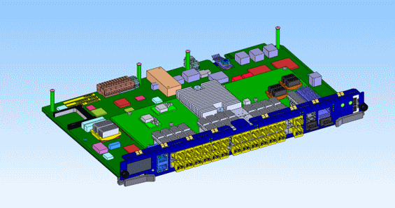
Simplify the heat flow path in the simulation by simplifying the solid geometry:
- Simplify or eliminate components away from the primary heat flow path.
- Eliminate any parts such as fasteners that are not critical to the heat flow path.
- Fill any holes created by eliminating irrelevant parts.
- Simplify components such as connectors, threaded stand-offs, and transformers.
- For sheet metal parts, get rid of the rounds resulting from the bends, and fill in or eliminate small features created by bend reliefs and the gaps resulting from rip corners.
- Eliminate interferences.
- Fill any irrelevant gaps. Many gaps in the CAD model come from standard manufacturing and assembly tolerances, but get closed on assembly.
Often, these simplifications can reduce the part count by 10% to 20%.

Air
The geometry of the air is determined by the cooling approach – forced or natural – and whether the internal air, external air, or both are involved.
- Fill the internal air space with one or more parts so that the internal air flow can be computed.
- For the external air in a system cooled by natural convection, represent any physical flow barriers in the air domain, such as walls, ceiling, floor, or table. Create a shape to let the air move around the domain in a sphere or hemisphere, where the outside faces represent the far-field conditions. Make the diameter of the sphere or hemisphere three to five times the length of the longest diagonal of the model.
- For a system cooled by forced convection, where the air blown through the system provides the cooling, the air typically enters through a well-defined inlet or inlets in the enclosure and exhausts through well-defined outlets. Identify or create a short inlet and extended outlet.
3D-CAD has several features to aid in the creation of the air, including the Extract Internal and Extract External Volume features, plus the set of Boolean features including Subtract, Unite, and Intersect. Use the Imprint feature so that all the contacts and interfaces are automatically created as you move down the simulation tree.
Natural convection example: Consider an external radio cooled by natural convection, where the radio fills an envelope approximately 200 mm on the diagonal, and is suspended in air far from any walls or other flow obstructions. To simulate this case, make a sphere around the radio that is at least 600 mm in diameter.
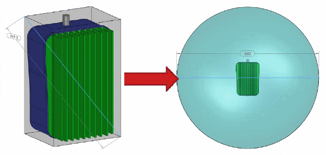
If the device is not suspended in the air, but instead is mounted on a wall, table, or ceiling, make a hemisphere like one of the following.

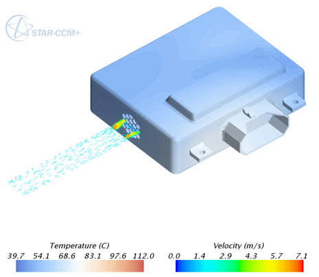
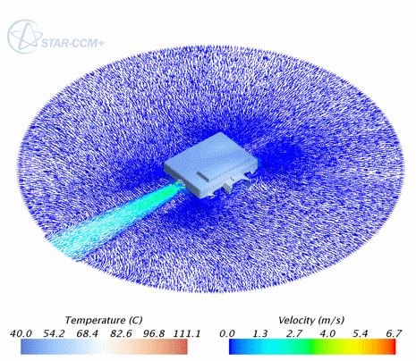
Forced convection example: Consider a device such as the one shown below, cooled by a fan that draws air in through two inlets and exhausts it out one.

There are two situations to consider:
- Not considering the air outside the module. Then, a simple short inlet and extended outlet suffice. Notice that the outlet is long enough for the flow to have time to be nearly uniform.
- Considering the outside air. Then the air domain looks very similar to a natural convection case.
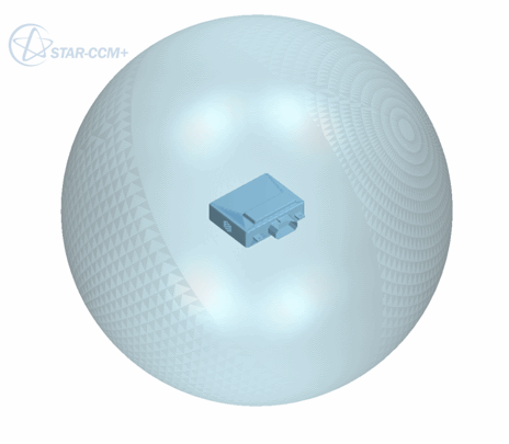
Notice from this example that the air pattern coming out of the outlet with the spherical external air quite closely resembles the extended outlet. The primary difference between the two involves the heat loss (or lack of it) through the exterior walls of the module.
Mesh Preparation
Mesh each solid that is part of the thermal path.
- When feasible, create a conformal polyhedral mesh across the air and solids, using the same mesh operation. A conformal mesh is good for both forced and natural convection situations. It is particularly good for natural convection situations because of some particulars related to the radiation calculations.
- Alternatively, for forced convection models, you can also mesh only the air as polyhedral (and conformal if multiple air parts are used) and mesh the solids using trimmed cells. As a result the overall mesh is non-conformal. This approach can be easier and faster to mesh, but is not recommended for cases using radiation.
Typical mesh sizes are 500,000 to 5,000,000 cells.
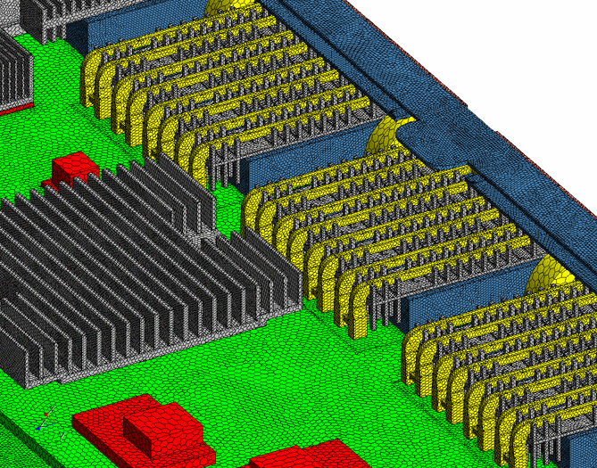
The example below shows a model with more than 500 parts with an efficient, fully conformal mesh.
Physics Set-Up
Assign properties to the air and the solids.
Air
Air density must vary with temperature, so use the Ideal Gas model.
Density variation with pressure is negligible, so the Boussinesq model is sufficient for modeling buoyancy effects with natural convection.
Solids
Assign thermal properties to solids:
- Many solids, including metals, are isotropic. For these, the default solid material assignment in Simcenter STAR-CCM+ is sufficient.
- Other solid parts, particularly printed circuit boards, are best described with orthotropic properties. Define the solid continuum as orthotropic, then specify the particular properties in the individual regions. The specific values depend on the number, thickness, and density of trace layers.
For a typical circuit board, values are kplanar ≈ 10 W/m-K and kthrough plane ≈ 0.5 W/m-K
- You can often assign properties to chips by describing the chip as a two-resistor thermal resistance network, using contact resistances. If you do not have any resistor network data, model the resistor as a ceramic such as aluminum oxide.
Boundary Conditions
Assign boundary conditions to the model for both heating and flow.
For both forced and natural convection:
- Assign temperatures on all air inlets and outlets.
- When applicable, assign a boundary condition that represents the heat exchange with the surrounding air.
- If there is no air surrounding the enclosure in the model (a common occurrence in forced convection cases), add convection on the boundary to model heat loss to the ambient:
- For external natural convection, h ≈ 5 – 10 W/m2-K
- For external forced convection, h > 20 W/m2-K
- Assign a heat power to every heat-dissipating component. Assign the thermal condition to the component region, calculating the power value as follows:
- Start with the actual power drawn by the component. This can be different from the power budgeted in the electrical design.
- Consider what the component does with the power:
- If the component is a power transistor or IGBT, it delivers most of that electrical power elsewhere.
- If the component is a radio chip or LED, it can be emitting the power as RF energy or visible light.
For forced convection, the three commonest cases are:
- Flow pushed into the system by fan or air supply at inlet. Specify:
- At inlets:
- Positive flow speed, positive pressure, positive mass flow rate, or fan pressure jump
- Ambient temperature
- At outlets:
- Pressure outlet boundary condition (0 Pa)
- Ambient temperature (for any reverse flow)
- At inlets:
- Flow pulled through system by fan or air supply at outlet. Specify:
- At inlets:
- Stagnation inlet boundary condition (0 Pa)
- Ambient temperature
- At outlets:
- Negative flow speed, negative pressure, negative mass flow rate, or fan pressure jump
- Ambient temperature (for any reverse flow)
- At inlets:
- Fan inside the system.
Use the fan interface option.
- Split out the boundary faces used to define the interface so that only the circular or annular faces are used as the boundaries for the specific interface.
- Set flow direction from Boundary-0 to Boundary-1, swapping boundaries on the interface as needed.
- Define the fan curve interface as a polynomial, OR
Input the fan curve using and then select the curve.
Specify:
- At inlets:
- Stagnation inlet boundary condition (0 Pa)
- Ambient temperature
- At outlets:
- Pressure outlet boundary condition (0 Pa)
- Ambient temperature (for any reverse flow)
For natural convection:
- Set the following convection conditions on the exterior air boundary:
- Stagnation inlet boundary condition (0 Pa)
- Total temperature = ambient temperature
- Set the following radiation conditions on the exterior air boundary:
- Boundary transparency = 1.0
-
Specify radiation temperature in the air continuum:
- Indoors: Radiation temperature = wall temperature.
- Outdoors: Turn on solar during the day. At night, radiation temperature = sky radiation temperature.
Solution Set-Up
Use the Segregated Energy and the Segregated Flow solvers. Set under-relaxation factors to:
- Fluid Under-Relaxation Factor = 0.99
- Solid Under-Relaxation Factor = 0.9999
Set Stopping Criteria to 300 to 500 iterations. This typically produces energy residuals under 1E-5 and moment residuals under 1E-8.
Models of 500,000 to 5,000,000 cells show good scalability up to 8 cores.
Results Monitoring
In general, monitor the same results you want to get from physical testing. Common results to monitor include:
- Residuals
- A 3-D image of the model showing temperature and velocity of flow
- Thermal resistance