Virtual Disk Model
The virtual disk model is based upon the principle of representing propellers, turbines, rotors, fans, and so on, as an actuator disk. The actuator disk treatment is practical when you are concerned about the influence of the rotor/propeller behavior on the flow rather than knowing about the detailed interactions between the flow and the blades of the rotating device.
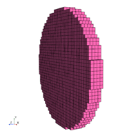
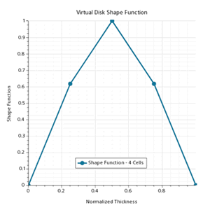
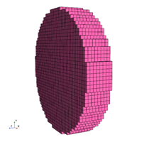
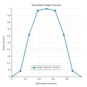
The action of the actuator disk on the flow field enters the momentum equations in the form of a source term. The source term distribution in the radial direction is given by the virtual disk method you select, whereas the distribution along the thickness direction is defined by a Gaussian shape function. Examples of such shape functions for different cell layer numbers are shown below. (With respect to the virtual disk's local coordinate system, the normalized thickness is along the z-axis and the radial direction lies in the x-y plane):
| 4 cell layers | 4 cell layers | 8 cell layers | 8 cell layers |
|---|---|---|---|
 |
 |
 |
 |
For the virtual disk model, there are currently four methods implemented:
| Note | The Gaussian shape function distribution along the thickness direction is not applicable for the User Defined Method. |
Body Force Propeller Method
The body force propeller method simulates the effect of a marine propeller. The method models the flow field interaction of the hull of a ship and the propeller. The flow that is induced by the propeller depends on the flow around the ship hull. Similarly, the hull flow is influenced by the propeller.
This method can be used as part of a DFBI (Dynamic Fluid Body Interaction) simulation. The method provides the advantage of a reduced mesh size and hence computational cost compared to performing a simulation that includes the propeller geometry. Use this approach if you do not require the detailed flow field around the propeller, but need only the correct propulsion specification.
- Definition of a virtual disk regarding position and direction in which thrust is produced
- Specification of a propeller performance curve
- Specification of an operating point (for example, rotational speed)
- Specification of an inflow method.
As a result, the distribution of the axial and tangential forces of the modeled propeller and its effect on the flow is calculated. The integration of these forces over the disk gives the thrust and torque of the propeller, which are available for the coupling with a DFBI simulation.
Blade Element Method
The blade element method is designed to analyze the complex flow field associated with helicopter rotors. The complexity of the flow arises due to the mutual aerodynamic interactions between the main rotor, the fuselage, and the tail rotor. The asymmetrical loading over the rotor disk complicates these interactions. A correct solution of the flow field around a rotor plays a crucial role in determining the aerodynamic characteristics and the performance of the helicopter.
The blade element method models the spinning rotor as a distribution of momentum sources. The strength of the source terms and their variations are interactively determined from the rotor geometry and the local velocity field. Although the blade geometry is not explicitly resolved, you are required to specify the blade geometry in terms of the chord and twist variations along the rotor radius. To describe the influence of the blade geometry on the flow you are expected to provide lift and drag coefficients for two-dimensional cross-sections of the blade at successive locations on the blade.
In forward flight, the rotor has an asymmetrical loading, which leads to undesired moments with respect to the rotor hub. To overcome this problem, a rotor trimming method is implemented that allows you to trim the rotor to the specified thrust and moments using a non-linear iterative approach.
The blade element method has numerous advantages over a transient rigid body motion approach for this application. This method eliminates the need for a body-fitted mesh along the blades while continuing to capture the wake structure. Intersecting or overlapping rotors are permitted, with no restriction on the number of rotors. Hence, you can study the interaction between the main rotor and the tail rotor of a single helicopter, or interactions between the rotor of several helicopters in a flying configuration.
This method is not restricted to helicopter applications — you can, for example, use it to study automotive radiator fans.
1D Momentum Method
The 1D Momentum model can be used to model the effect of a wind turbine on its surroundings. Wind turbines convert wind energy into mechanical energy of rotation, which is used to generate power. Among the wide variety of types of wind turbine, the 1D momentum method is restricted to so called Horizontal Axis Wind Turbines (HAWT). These turbines use aerodynamic lift to drive a rotor mounted on a horizontal axis.
The 1D Momentum method is based upon one-dimensional momentum theory with wake rotation. The method imitates the effect of the presence of a wind turbine by adding a source term to the momentum equations that account for both axial and tangential effects. For more information on the formulation, see 1D Momentum Method.
This method requires wind turbine performance curves that provide the thrust coefficient and power as a function of wind speed. An inflow velocity plane upstream of the wind turbine computes volume-averaged values of air velocity and density. The upstream velocity is used to extract the thrust coefficient and the power values from the performance curves and to calculate the source term.
The method can be used to study wake effects of a single turbine or of a complete wind park. A typical wind park design objective is to avoid placing a wind turbine in the wake of another. The 1D momentum method is particularly useful for examining wind park layouts in order to maximize energy production.
User Defined Method
The user defined method of the virtual disk model is designed to model the action of a rotating device by specifying a user-defined volume force on a three dimensional cylindrical mesh.
The method uses the core components of the virtual disk framework, that is, the virtual disk geometry to specify the size, location, and orientation of the rotating device. For this disk geometry, you specify a resolution for the three-dimensional cylindrical mesh. With this resolution, the three-dimensional virtual disk is subdivided into mesh elements or "buckets". The points on this virtual disk mesh correspond to the cell centers of the elements on the cylindrical mesh. An inflow velocity plane samples velocity and density information from the flow field to make it available on the virtual disk mesh. After preparing the virtual disk mesh, you specify a volumetric source term of elements of that mesh. To specify the source term, several methods are available including user coding.