Fans and Blowers
Simcenter STAR-CCM+ provides models for axial and radial fans where classical fan laws apply.
Simcenter STAR-CCM+ provides the following methods for modeling fans:
-
The Fan Interface
The fan interface is a simple model that represents the fan by a zero-thickness interface and imposes a pressure jump across the interface. This model can also add swirl to the downstream flow. The model is an implicit implementation that provides quicker convergence than the fan momentum source.
-
The Blower Interface
The Blower interface lets you model two types of radial fans: centrifugal fans and impeller fans.
-
The Fan Momentum Source
The fan momentum source is a more complex model than the fan interface. This model can add swirl to the downstream flow, and is applied to a region that represents the three-dimensional volume of the fan. The fan momentum source model uses an explicit implementation, and as such, is slower to converge.
The fan interface and the fan momentum source are simple models that trade accuracy for speed. To obtain more accurate results you can model the individual blades of the fan using either moving frames of reference (MRF) or mesh motion. See Advanced Methods for Modeling Fans.
| Note |
The fan interface models in Simcenter STAR-CCM+ are designed for electronic cooling applications that usually involve incompressible flow. Additionally, they can be used for ventilation systems involving low speed flows. Using these models for moderate to high Mach Number flows does not give the desired results. |
For the theory that Simcenter STAR-CCM+ uses in computing the fan interface and fan momentum sources, refer to the Fan Interface formulation and the Fan Momentum Source formulation.
If you are interested in modeling the acoustic effects of a fan, refer to recommended practices for modeling acoustic sources in axial fans.
The Fan Interface Model
The fan interface is a simple model that provides quicker convergence than the fan momentum source. It models the pressure rise through an axial fan as a function of local flow rates or velocity.
In axial fans, the outflow direction is the same as the inflow direction. However, in radial fans (or blowers), the outflow direction is not the same as the inflow direction. These types of fans are modeled using a blower interface.
The fan interface models the fan as a circular interface of zero thickness, although there is no restriction on the topology that you use. This interface type is used only between regions belonging to the same fluid continuum.
When you set up a fan interface, you supply the fan performance curve that corresponds to the physical fan that you are modeling. The fan performance curve specifies the pressure drop across the fan interface as a function of one of the following variables:
- Local velocity
- Mass average velocity
- Volumetric flow rate
- Mass flow rate.
See Using the Fan Interface, Creating a Fan Interface, and Fan Interface Properties. For a worked example, see the tutorial Multi-Part Solid: Graphics Card Cooling.
The Blower Interface Model
The Blower interface lets you model two types of radial fans: centrifugal fans and impeller fans.
In axial fans, the outflow direction is the same as the inflow direction. These fans are modeled using a fan interface. However, in radial fans (or blowers), the outflow direction is not the same as the inflow direction. These types of fans are modeled using the blower interface.
The blower interface implementation in Simcenter STAR-CCM+ is the same for both centrifugal fans and impeller fans, except that swirl at the outflow is allowed for impeller fans only.
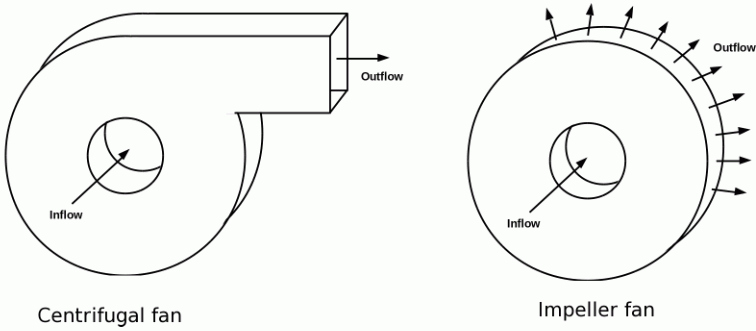
For radial fans, the pressure rise is implemented across two non-contiguous boundaries (the blower inlet(s) and exit), so the Blower interface is an indirect interface.
Fan Momentum Source Model
The fan momentum source employs an “actuator disk” type of methodology.
With this methodology, the detailed geometry of the fan blades is not modeled. The circular fan disk is meshed as a separate region, and Simcenter STAR-CCM+ identifies the cells that are in the volume swept out by the fan blades. The appropriate momentum sources, including the swirl component, are applied to these cells. Analysis is steady, so blade passing effects are not included.
The fan momentum source model can simulate the most commonly designed axial fans. The model works well for adverse pressure gradients, where the fan is pushing against a back pressure. You can have more than one fan in the same simulation.
Since the momentum sources are based on theory, there is no guarantee that the resulting flow rate and pressure rise lies in the fan curve of a particular fan. You specify the appropriate fan performance curve. Simcenter STAR-CCM+ automatically adjusts the momentum sources so that the operating point of the simulated fan falls on the fan curve.
The fan momentum source model uses an explicit implementation, and as such, can be slow to converge.
Advanced Methods for Modeling Fans
To model fans more accurately, you can model a region that contains the geometry of the fan blades. Use the following methods:
- Rotating Reference Frames
A rotating reference frame is a rotating frame of reference that can be applied to regions to generate a constant grid flux.
This approach gives a solution that represents the time-averaged behavior of the flow, rather than the time-accurate behavior. For more information, see Using Moving Reference Frames in Steady-State.
- Unsteady Sliding Mesh
When the time-accurate behavior is required, Simcenter STAR-CCM+ provides the option to move the mesh vertices of a region during a transient analysis. This mesh motion is specified using either a Rotation motion or a Rotation and Translation motion.
Applying either of these motions results in mesh vertices being displaced in each time step. For more information, see Simulating Rigid Motion. For a worked example, see the tutorial Moving Reference Frames: Rotating Fan.
Both the moving reference frame and unsteady sliding mesh approaches to fan modeling require that you create a separate region for the moving fan blades. The joins of the regions are interfaces. Conformal meshes are preferred but are not required.
You can use either trimmed cell or polyhedral meshes:
- For polyhedral meshes, all regions can use the same mesh operation, and the mesh is conformal across the interface.
- For trimmed cell meshes, each region must have its own mesh operation, and the mesh is not conformal across the interface.