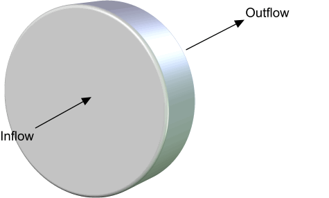
Axial Fans
Simcenter STAR-CCM+ provides two approaches to modeling axial fans: the fan momentum source and the fan interface. The primary objective of these approaches is to model the increase in pressure across the fan.
Additionally, these approaches can model the swirl that is introduced by the fan. None of these approaches take into account the detailed geometry of fan blades. Generally, the fan interface is more robust, and it is usually recommended over the fan momentum source.

Fan Interface
The fan interface is a simple model that represents an axial fan by a zero-thickness interface and imposes a pressure jump across the interface. The fan interface can also add swirl to the flow downstream of the fan.
- Pressure Jump Modeling
- The pressure jump across the interface is obtained from a user-specified fan curve that plots pressure jump as a function of flow rate or flow velocity. The pressure jump that is read from the fan curve can be interpreted in two ways. One option is:(5025)
where is the static pressure downstream of the fan and is the total pressure upstream of the fan. This option appears as Standard in Simcenter STAR-CCM+.
The other option is:
(5026)where is the static pressure upstream of the fan. This option appears as Static to Static in Simcenter STAR-CCM+.
The pressure jump is usually imposed locally, which means that a separate pressure jump is applied to each pair of faces on the fan interface. Simcenter STAR-CCM+ also provides the option to apply a single pressure jump to all face pairs on the fan interface.
- Swirl Modeling
-
Assuming that the axial velocity, the radial velocity, and the density are unchanged across the fan, the total pressure jump across the fan is related to the static pressure jump , which is derived from the performance curve, as:
(5027)where is the total pressure downstream of the fan interface and is the swirl velocity, which corresponds to the tangential component of the velocity vector.
The fan efficiency is given as:
(5028)where is the volumetric flow rate, is the mass flow rate, is the fan rotation rate, and is the radial distance from the axis of the fan.
With:
The swirl velocity difference is then obtained as:
(5029)Rearranging Eqn. (5029) and inserting Eqn. (5027) gives the following quadratic equation in :
(5030)That is solved for :
(5031)Simcenter STAR-CCM+ uses only the negative square root. In the case of a complex root, Simcenter STAR-CCM+ uses only the real part.
Fan Momentum Source
The fan momentum source employs an actuator disk type of methodology. Actuator disk models model the fan as a volumetric region and introduce sources in the momentum equation to model pressure rise and swirl. Various actuator disk models differ in how the sources are computed. The fan momentum source approach does not take into account the detailed geometry of the fan blades when computing source terms.
The fan momentum source enters the momentum equation Eqn. (665) as volumetric body force.
- Axial Component of Source Term for Pressure Rise Modeling
-
The axial component of the source term that is added to the momentum equation controls the pressure rise through the fan region.
At each time step, the net volume flow rate is calculated from the upstream boundary to the downstream boundary of the fan region, and the corresponding pressure rise is obtained from the fan curve. This pressure rise is the target pressure rise that the fan must achieve for the current mass flow rate. The pressure rise is computed over the entire length of the fan region, therefore, the target pressure rise per unit length is given by:
The axial component of the momentum equation source term is calculated as:
(5033)where is a unit vector in the axial direction of the fan and:
(5034)where is the pressure that is averaged over the boundary downstream of the fan region and is the pressure that is averaged over the boundary upstream of the fan region.
- Tangential Component of Source Term for Swirl Modeling
-
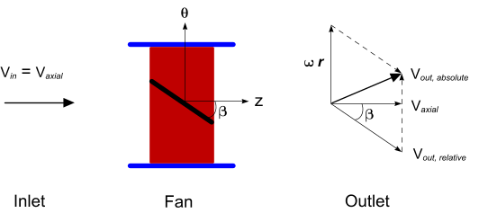
To understand the forces that the fan blades impart to the fluid, consider the velocity vector diagram below. The fan axis is aligned in the z-direction. A single fan blade is shown in the fan volume.

Fluid approaches the fan with velocity , which is assumed to be uniform and to have no tangential component . The fan rotates in the tangential -direction with the angular velocity . The fan blades are at an angle to the fluid flow and are assumed to have no curvature.
The fluid velocity leaving the fan, , is the vector sum of the relative velocity (assumed to be parallel to the blade angle) and the rotational velocity , imparted to the fluid by the fan blades.
From the previous vector diagram, the tangential velocity component can be calculated as:
(5035)where is the radius measured from the center of the fan.
is calculated as the average of the target tangential velocity at the downstream fan boundary. The average of the actual tangential velocity is calculated as:
(5036)where is a unit vector in the tangential direction.
A numerical factor is defined as:
(5037)The numerical factor drives the code to achieve the , and has units of .
Finally, the tangential part of the source term addition to the momentum equation is:
(5038)where is the normalized distance of the current cell from the fan upstream boundary, calculated along the fan axis. The term ensures that the swirl increases gradually in the fan region.