Idealizations
In many simulations, it is common practice to reduce the size of the computational domain using planes of symmetry, axes of rotation, periodicity, or by reducing the 3D domain to a 2D domain. However, when you calculate physical quantities using reports you generally want to account for the whole domain. You can obtain report values for the full model using idealizations.
Extrusion Idealization
The extrusion idealization allows you to evaluate a report on a 3D domain that is obtained by extruding the 2D region. To define the extrusion, you specify the extrusion thickness and the helical pitch, which is the angle of rotation per unit extrusion thickness.
where , , and are the components of the idealized vector in x, y, and z respectively; is the de-idealized vector; is the total extrusion thickness, and and are defined as follows:
is the total helical pitch over the extrusion thickness.
If you specifiy a negative extrusion thickness, the 2D region is extruded a distance of in the direction of the idealization coordinate system. Simcenter STAR-CCM+ considers the signed value of to compute the change in ; this ensures that a positive helical pitch always represents a counter-clockwise twist along the postive direction.
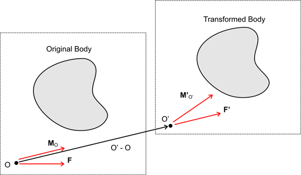
When you apply the idealization to a moment or magnetic torque report with helical extrusion, the idealized force is translated to the axis of rotation of the helical extrusion. The translated force results in a new moment. The force and new moment are transformed according to Eqn. (5240). The transformed force is translated back to the original moment origin, which results in an additional term in the new moment calculation. For more information, see Transformation of Moments.
Periodic Idealization
Periodic idealizations are created whenever periodic interfaces are detected in a boundary interface. The periodic idealization allows you to evaluate reports for the whole geometry, when only a short repeating segment of the geometry is modelled. For more information, see Periodic Interface Topology.
When a periodic idealization is applied to a scalar report, the scalar is multiplied by the number of periodic repeats (that is, the number of repeated segments that capture the full model), . The number of periodic repeats is equal to 360 degrees divided by the periodic repeat angle (the internal angle of the repeated segment). The result is not well-defined if the periodic repeat angle is not a factor of 360.
If the periodic idealization is applied to a vector, copies of the vector are produced where each copy is rotated by the periodic repeat angle relative to the previous copy. The resultant vectors are added to obtain the idealized report vector. For example, a periodic repeat angle of 60 degrees produces 6 copies of the original vector report (rotated at 0, 60, 120, 180, 240, and 300 degrees).
For reports that calculate moments, the formulation is the same as for vectors but also accounts for the transformation of the moment origin when the moment vector is rotated.
Symmetric Idealization
Symmetry idealizations are created whenever Simcenter STAR-CCM+ detects a symmetry boundary. The symmetry idealization allows you to evaluate reports for the whole geometry, when only a small part, enclosed by lines of symmetry, is actually modelled.
When applied to a scalar quantity that scales with the extent of the input parts, such as volume integrated quantities, the idealization multiplies the quantity by (where n is the number of symmetry planes).
For vector quantities, such as forces, Simcenter STAR-CCM+ successively reflects the vector across each symmetry plane and adds the reflected vectors to the original vector computed.
- Reflects the force vector by neglecting the out-of-plane components.
- Refects the moment by neglecting its in-plane components.
- Reflects the moment origin by neglecting its out-of-plane coordinate relative to the symmetry plane.
- Computes the moment of the reflected force about the original moment origin to obtain the translation term.
- Adds the reflected moment and the translation term to the original moment computation.
- Adds the reflected force to the original force.
- Uses the force and moment obtained as the force and moment input to compute the idealization over the next symmetry plane.
Transformation of Moments