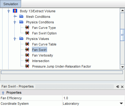
Modeling the Fan Swirl
You can model the fan swirl in your simulation.
You can use either the Calculated option, based on Eqn. (5031), or the User-Specified option to calculate the swirl downstream of the fan. By default, fan swirl is not included.
For more information, refer to the Fan Interface formulation.
To include the fan swirl in your simulation:
- Expand the node, and click Fan Swirl Option.
-
In the
Properties window, select
Calculated or
User-Specified from the
Fan Swirl Option drop-down menu.
If you select Calculated, the Fan Swirl node is added to the Physics Values.
If you select User-Specified, the Specified Fan Swirl node is added to the Physics Values.

-
In the
Properties window, set the appropriate values.
Table 1. Fan Swirl Properties Fan Efficiency Specify the fan efficiency, in Eqn. (5028). Coordinate System Select the appropriate coordinate system. Types other than Laboratory are not available for selection until you create them. You can use any of the coordinate system types for fan modeling, but the following restrictions apply:- The origin of the coordinate axes must coincide with the center of rotation of the fan.
- The z-axis must run along the fan axis and be oriented in the fan-flow direction.
Table 2. Specified Fan Swirl Properties Method Selects the input for the fan swirl value as a vector profile. Dimensions The units of the fan swirl value (read-only). Coordinate System Select the appropriate coordinate system. Types other than Laboratory are not available for selection until you create them. You can use any of the coordinate system types for fan modeling, but the following restrictions apply:- The origin of the coordinate axes must coincide with the center of rotation of the fan.
- The z-axis must run along the fan axis and be oriented in the fan-flow direction.