Blower Interface Properties
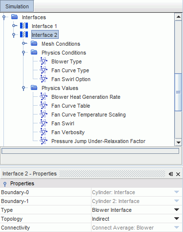
This section describes the properties and physics values that you can specify for a blower interface.
The Blower Interface node has properties, conditions, values, and a pop-up menu.

Blower Interface Properties
The properties of a Blower Interface node are listed below. These properties cannot be modified.
|
Boundary-0 |
Specifies the upstream boundary of the blower interface (Read Only) |
|
|
Boundary-1 |
Specifies the downstream boundary of the blower interface (Read Only) |
|
|
Type |
Specifies the type of interface: Blower Interface. |
|
|
Topology |
Defines the connection type between the interfaces. Only the Indirect type is possible. |
|
|
Connectivity Option |
Shows how the boundaries on two sides of the interface are connected. Only Connect Average connectivity is possible. |
|
Blower Interface Conditions
You can specify the following physics conditions for a Blower interface:
|
Blower Type |
Specifies the blower type according to the fan geometry. |
|
|
Centrifugal |
You set the fan curve type and specify the fan performance curve. |
|
|
Impeller |
You set the fan curve type and specify the fan performance curve, and can optionally specify the fan swirl. |
|
|
Fan Curve Type |
The fan performance curve specifies the pressure rise across the blower interface. |
|
|
Polynomial |
The fan curve is defined as a polynomial function. |
|
|
Table |
The fan curve is defined as a table of pressure versus flow rate values. |
|
|
Fan Swirl Option |
The option to add swirl to the flow is available only for blowers of the Impeller type. |
|
|
Calculated |
The Fan Swirl node is added to the Physics Values, where you specify the appropriate coordinate system and blade angle. The swirl is calculated accordingly and added to the flow. |
|
|
No Swirl |
No swirl is added to the flow. |
|
Blower Interface Values
You can specify the following physics values for a Blower interface:
|
Blower Heat Generation Rate |
Specifies the heat that is generated by the blower per unit time. This heat is added to the flow that exits the blower. This option is available only when an energy model is activated in the physics continuum. |
|
|
Fan Curve Table/Polynomial |
Specifies the fan curve performance using a table or a polynomial, according to the Fan Curve Type that is specified in the physics conditions. See Specifying the Fan Performance Curve as a Polynomial Function. |
|
|
Fan Curve Temperature Scaling |
Scale the fan performance curve using data temperature. This option is available only when an energy model is activated in the physics continuum. |
|
|
Fan Swirl |
Specifies the coordinate system and the blade angle that are used to compute the flow swirl for the impeller fan. See Blower Swirl Values. |
|
|
Fan Verbosity |
Activate or deactivate the reporting of fan operating point details in the Output window. |
|
|
Pressure Jump Under-Relaxation Factor |
Specifies an under-relaxation factor between 0 and 1 to improve convergence. |
|
Blower Swirl Values
You can specify the following values:
| Coordinate System |
The coordinate system that is used to specify the impeller orientation and its rotation direction. Types other than Laboratory are not available for selection until you create them. You can use any of the coordinate system types for impeller fan modeling, but the following restrictions apply:
|
|
| Blade Angle |
The blade angle () of the impeller fan:
|
|