Moving Reference Frame
In Simcenter STAR-CCM+, a moving reference frame indicates a user-defined rotating or rotating and translating reference frame.
Applying a moving reference frame to a region does not change the position of cell vertices. But rather it generates a constant grid flux in the appropriate conservation equations. This grid flux is calculated based on the properties of the reference frame rather than the local motion of cell vertices.
This modeling approach converts the transient motion to an time-averaged solution. It does not provide a time-accurate solution, regardless of the time model in use.
For the governing flow equations in a moving reference frame, see Reference Frames.
Moving reference frames are usually applied to steady state cases. You could also apply it in transient cases to a certain region, where the transient effect is not relevant for the entire simulation.
| Note | Do not use moving reference frames if any considerable component of external flow velocity is perpendicular to the axis of rotation. |
The moving reference frame gives physically realistic results only if the flow in the surrounding volume is axisymmetric. If any component of the surrounding flow is perpendicular to the axis of rotation, unphysical results proportional to the perpendicular component follow.
- Frozen Rotor Approach
- Mixing-Plane Approach
In a frozen rotor simulation, a rotating reference frame is applied to the region of mesh containing the rotor blades. The remainder of the mesh is either static or has a different rotating reference frame applied (as multiple regions can have different reference frames). As the rotor blades are frozen in space with respect to the stator blades, the flow field that the stator blades see depends on the relative position of the stages. Different relative positions result in different solutions, which is a major disadvantage of this approach.
At the interface between regions that are assigned to different reference frames, local variable values are transformed from one reference frame to the other on a cell-by-cell basis. The transformed variable values are used to compute the fluxes at the interface boundary of the neighboring region. Since no true mesh motion is involved, the position of a moving object relative to a neighbouring region is unchanged. Consequently, transient flow effects due to a change in position are neglected. This approach corresponds to taking a snapshot of the instantaneous flow field with the moving object in that particular position.
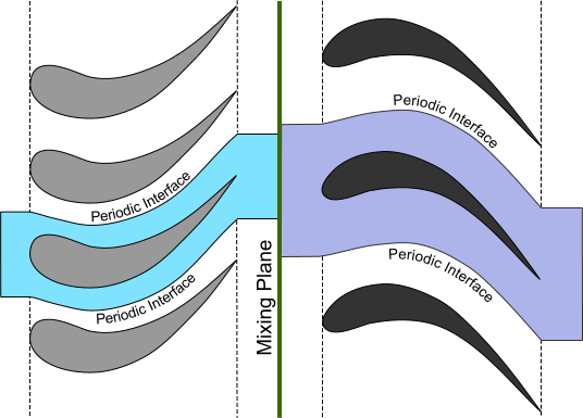
In a mixing plane analysis, the problem of relative positioning is overcome by using an indirect mixing plane interface to couple the rotor and stator regions. Flow conditions on either side of the mixing plane interface are averaged circumferentially to provide a single radial profile that is applied to all cell faces at the interface. The basis for this treatment can be appreciated by considering what would be observed when looking at a fast rotating fan: that is, a single rotating surface emitting a constant stream of air independent of blade position. Increasing the number of blades on the fan, increasing the rotational speed, or simply moving farther away from the fan, would all tend to increase the accuracy of this interpretation. The following figure illustrates a rotor and stator assembly for which a mixing plane simulation would be appropriate. If periodic interfaces are applied mid-way between the blades, it is only necessary to include a single blade passage for each stage.

Place the mixing plane interface at a point where the time-averaged properties rather than instantaneous flow details are likely to influence the flow. To create the mixing plane interface, see Creating a Boundary Interface. Select the newly created node under Interfaces and set Type to Mixing-Plane Interface.
The mixing plane approach has the advantage that the relative positioning of the stator and rotor is irrelevant. However, it suffers from the fact that wake effects are lost due to the circumferential averaging. If it becomes necessary to model the interaction between stages in greater detail, Simcenter STAR-CCM+ provides two further options: rigid motion of mesh vertices in a transient analysis, or a harmonic balance analysis of a single stage with a prescribed wake.