Reference Frames
Mesh motion is defined with respect to a reference frame, which can be stationary (laboratory reference frame) or rotating and translating relative to the laboratory frame. In steady simulations, or in transient simulations that do not require a time-accurate solution, moving reference frames provide a way of modeling rotations and translations as a steady-state problem, while leaving the mesh stationary.
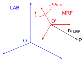
The velocity of a material point P with respect to the moving reference frame (also called the relative velocity) can be written as:
where is the velocity in the laboratory reference frame (also called the absolute velocity), is the moving reference frame translation velocity, that is, the velocity of its origin with respect to the laboratory frame, is the angular velocity of the moving reference frame with respect to the laboratory frame, and is the position vector of the material point with respect to the moving reference frame.
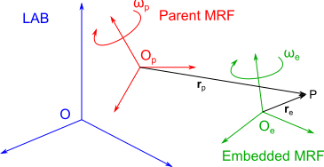
with
where is the angular velocity of the parent reference frame, as measured in the laboratory reference frame, is the angular velocity of the embedded reference frame, as measured in the parent reference frame, is the position vector with respect to the parent reference frame, and is the position vector with respect to the embedded reference frame.