1D Momentum Method
A wind turbine extracts mechanical energy from the kinetic energy of the wind. It acts as an actuator disk, slowing down the wind speed from to at the rotor plane, and further slowing it down to in the wake. Moving upstream to downstream, the velocity decreases and the streamlines diverge to comply with continuity.
The 1D momentum method adds a source term to the momentum equations to model the effects of a wind turbine. The source term accounts for both the axial and the tangential effects as given by the Ideal Horizontal Axis Wind Turbine (HAWT) with wake rotation. When wake rotation is included in the analysis, the induced velocity at the rotor consists of an axial component and a tangential component acting in the rotor plane.
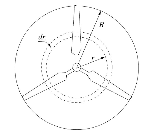
The formulation is based on the use of an annular stream tube with a radius and a thickness . (Note that this is not the disk thickness.) This definition results in a cross-sectional area of . The following figure shows the schematics and the notation that is used in the formulation:
Thrust Distribution
Total thrust of a wind turbine is given by:
Thrust on an annular ring of width at a radius is:
The theory assumes an infinitesimally thin disk with zero thickness, whereas the source terms are added for a virtual disk of a finite thickness . Therefore, the elemental thrust is to be understood as thrust per annulus per unit disk thickness :
Using Eqn. (5007), this can be rewritten as:
Thrust per unit volume within the annulus thus reads:
where is the geometrical volume of the disk.
Thrust per unit volume is independent of . Thrust depends on quadratically, but the volume of each ring also increases quadratically with , so thrust per unit volume is constant. For each cell within a ring:
Eqn. (5012) needs to be scaled, because not all cells are fully within the disk. The scaling factor is:
where
The thrust per cell is given by:
corresponds to the axial force for a given cell, whose cell center lies within the virtual disk.
Torque Distribution
The torque distribution corresponds to the calculation of the tangential force. With a given velocity at the inflow plane , the power delivered by the wind turbine can be extracted from the user specified power curve table or polynomial. From this value, the torque is evaluated as:
where is the rotation rate. This torque is distributed as tangential force over the disk cells.
The elemental torque for an annular ring of width and thickness are obtained by applying the conservation of angular momentum. On an annular ring element, this gives:
Since and , the expression for the elemental torque reduces to:
Integrating Eqn. (5015):
The torque now is:
To derive an expression for torque per unit of annular ring volume, Eqn. (5015) is rewritten by use of Eqn. (5017):
Torque per unit volume of annular ring is then:
Torque for each cell within the annular ring is:
Scaling needs to be applied, because . The scaling factor reads:
With scaling applied:
With , Eqn. (5022) can be further simplified:
The tangential force for a given cell whose cell center lies inside the virtual disk is given by:
The axial and the tangential forces are used to assemble a source term vector with respect to the laboratory coordinate system. This source term is then added to the momentum equations.