Positioning Tool

The Positioning Tool allows you to place Construction Geometries and QuickParts in reference to each other.

The following options are available:

  • Align—turns and moves an object until it is aligned with another object.
  • Rotate—turns an object around a specified axis.
  • Translate—moves an object from one position to another.

The following properties characterize the different positioning options:

Align—Properties

Target Objects Specifies the Construction Geometries or QuickParts you want to align.
Align By Controls the alignment mode. The following options are available:
  • Face, Edge, Vertex

    Aligns the Target Objects with a geometric entity—face, edge, or vertex—of another QuickPart.

    • Reference: Specifies a geometric entity of the reference QuickPart.
    • Target: Specifies a geometric entity of the Target Objects.

    You select the reference and target entities interactively in the Graphics window (highlighted in ochre and green, respectively). After the selection, the calculated Angle between the selected entities is displayed.

    • Align: Rotates the Target Objects about its local origin (see X_ref, Y_ref, Z_ref in the Graphics window) to end up in a position where the selected geometric entities are parallel to each other. The vector normals of the selected entities point in the same direction.
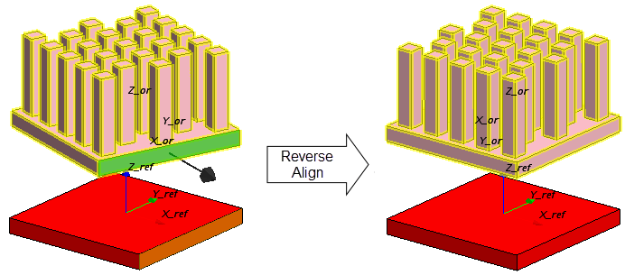
    • Reverse Align: As Align with the vector normals of the selected entities pointing in opposite directions.
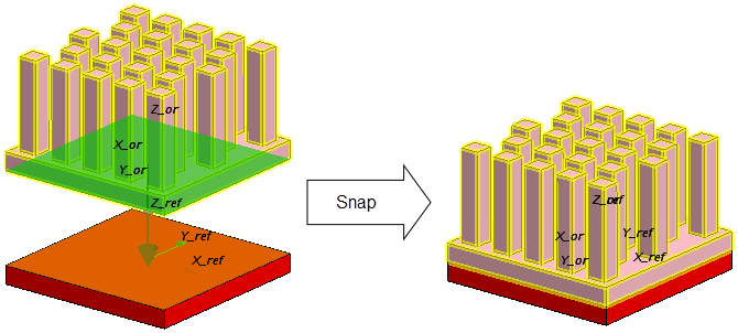
    For aligned geometric entities, Snap translates the Target Objects to end up in a position where the selected geometric entities are in contact. Distance displays the magnitude of the translation vector.
  • X-Axis, or Y-Axis, or Z-Axis: Aligns the Target Objects with the x-, y-, or z-axis of a Coordinate System that you specify.
    • Set Reference Axis Face: Specifies a face of the Target Objects.
    • Coordinate System: Specifies the laboratory coordinate system or a local coordinate system of another QuickPart.

    The Target Objects are rotated about its local origin (see X_ref, Y_ref, Z_ref in the Graphics window) to end up in a position where the respective axis is normal to the selected face.

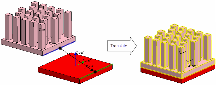
Example: Positioning of a heat sink on a block-shaped chip.


Rotate—Properties

Target Objects Allows you to select the Construction Geometries or QuickParts you want to rotate.
Rotation Vector Defines the direction vector of the axis of rotation. The following options are available:
  • Enter the X, Y, and Z components of the direction vector, in the selected Coordinate System.
  • Determine the direction vector interactively within the Graphics window by selecting one of the following entities (highlighted in orange):
    • Edge: sets the rotation vector collinear to the edge.
    • Face: sets the rotation vector equal to the face normal.
Rotation Position Defines the origin of the axis of rotation. The following options are available:
  • Enter the X, Y, and Z components of the origin, in the selected Coordinate System.
  • Determine the origin interactively within the Graphics window by selecting one of the following entities (highlighted in pale blue):
    • Face: sets the origin to the center of the face.
    • Edge: sets the origin to the midpoint of the edge.
    • Vertex: sets the origin to the vertex location.
Angle Specifies the angle of rotation. The following options are available:
  • Enter the angle value directly.
  • Determine the angle interactively within the Graphics window. The rotation angle is calculated From one point To another, where the point locations depend on the selected entities (highlighted in dark blue and green, respectively):
    • Face: sets the point to the center of the face.
    • Edge: sets the point to the midpoint of the edge.
    • Vertex: sets the point to the vertex location.
Coordinate System Defines the coordinate system for the rotation. You can define the rotation in the Laboratory coordinate system or in the local coordinate systems of another QuickPart. See X_ref, Y_ref, Z_ref in the Graphics window.

Example: Positioning of a heat sink on a block-shaped chip.


Translate—Properties

Target Objects Allows you to select the Construction Geometries or QuickParts you want to translate.
Translation Vector Defines the direction and distance of translation. The following options are available:
  • Enter the X, Y, and Z components of the translation vector, in the selected Coordinate System.
  • Determine the translation vector interactively within the Graphics window. The direction and distance is calculated From one point To another, where the point locations depend on the selected entities (highlighted in dark blue and green, respectively):
    • Face: sets the point to the center of the face.
    • Edge: sets the point to the midpoint of the edge.
    • Vertex: sets the point to the vertex location.
Coordinate System Defines the coordinate system for the translation. You can define the translation in the Laboratory coordinate system or in the local coordinate systems of another QuickPart. See X_ref, Y_ref, Z_ref in the Graphics window.

Example: Positioning of a heat sink on a block-shaped chip.