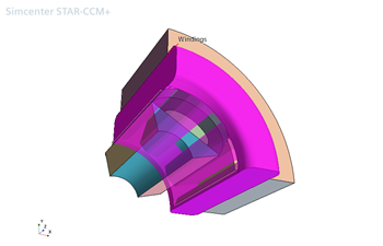
Windings
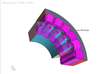
The geometry definition file can include information on stator windings, but not rotor windings. Simcenter STAR-CCM+ imports stator windings as either bulk or single-tooth windings, as defined in the geometry definition file. Simcenter STAR-CCM+ constructs 3D rotor windings as single-tooth windings from the field coil bodies of the 2D geometry.
| Bulk Winding | Single-tooth Winding |
|---|---|
 |
 |
The height of the bulk winding is the length of the toroidal portion of the winding in the axial, or Z-direction. This height is calculated by multiplying the slot width (radial slot opening distance) with the average winding span of the machine (that is, the value of the go slot minus the return slot) divided by four.
Any winding information for stator geometries that contain individual conducting wires or insulators is currently ignored. For these geometries, Simcenter STAR-CCM+ does not create any bulk or single-tooth windings.
For the imported 3D geometry (the Thermal Model), Simcenter STAR-CCM+ also constructs 3D rotor field windings from the field coil bodies of the corresponding 2D geometry (the EMAG Parts). Rotor windings are always constructed as single-tooth windings.