Lighthill Wave and Perturbed Convective Wave Modeling: Simplified HVAC Duct
Noise generated by the air handling components in heating, ventilation, and air conditioning (HVAC) systems is a large contributor to interior cabin sound levels. Investigating the sources of noise and modifying the design accordingly, leads to better and quieter systems.
The purpose of this tutorial is to investigate the aerodynamic generation and propagation of sound within a simplified HVAC duct. You use hybrid aeroacoustics models—the Lighthill Wave model and the Perturbed Convective Wave model—to resolve acoustic waves up to a frequency of 2.5 kHz. Both models solve additional wave equations for the sound based on source terms from the flow.
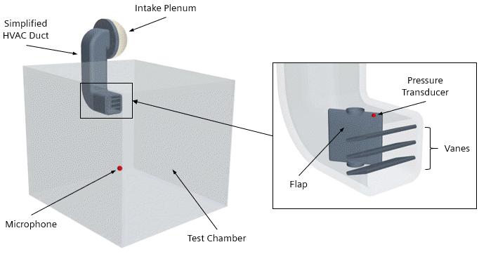
The geometry for this tutorial consists of a generic HVAC duct, depicted as follows:

Air enters the HVAC duct through an intake plenum with a constant density of 1.18415 kg/m^3 and a mass flow rate of 0.0075 kg/s. Inside the HVAC duct, a flap and three vanes control the air as it flows into the test chamber. The boundaries of the test chamber are modeled as pressure outlets with a pressure of 0 Pa. The speed of sound in the far field is 346.5 m/s, which corresponds to an ambient temperature of 25 °C.
You run the tutorial in three steps:
- You perform a steady-state flow simulation with a Reynolds-Averaged Navier Stokes (RANS) turbulence model using a relatively coarse mesh. You use the computed Taylor Micro Scale to determine the cell size that is required to resolve the turbulent noise sources inside the HVAC duct. Additionally, you use the solution to initialize the subsequent simulations.
- You refine the mesh and perform an unsteady aeroacoustics simulation with LES using the Lighthill Wave model.
- You re-run the aeroacoustics LES simulation using the Perturbed Convective Wave model.
Pre-defined simulation operations allow you to automate the solution process.
After the two aeroacoustics simulations are complete, you compare the simulation results to gain insight into the capabilities of the two modeling approaches. You perform spectral analyses of the time signals received at a microphone in the test chamber and at a pressure transducer on the duct wall.