Magnetic Vector Potential: Axial Flux Motor
This tutorial demonstrates how to use the Finite Element Magnetic Potential Vector model to solve for the magnetic flux produced by the magnets of an axial-flux motor.
An axial-flux, or “pancake”, motor is a disc-type electric motor where magnets are arrayed on a rotor around a central shaft. This type of motor is typically used in applications that require a short axial length, for example in elevators where the lifting gear is located inside the elevator shaft.
The main flux in an axial-flux motor passes through an air gap between the rotor and stator in a direction parallel to the axis of rotation. The three-dimensional magnetic flux distribution the motor produces is difficult to calculate using analytical methods.
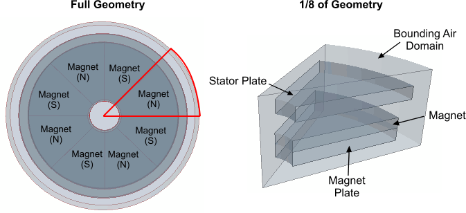
This simulation models 1/8 of a slotless permanent-magnet brushless motor, surrounded by air. In the full geometry, magnetic poles of opposite polarity (north and south) alternate around the central shaft. In the reduced geometry, you model a single magnetic pole and use antiperiodic interface conditions to account for the change in polarity.

The windings, which would be located in the gap between the rotor and the stator, are not shown, as they are not used in the simulation.
Analysis Overview
| Geometry | 1/8 of the full geometry |
| Mesh |
|
| Materials and Physics |
Materials:
Main Physics Models:
|
| Boundary Conditions | Anti-Symmetry Perfect Electric Conductor (PEC) assumption for all boundaries. |
| Interfaces |
|
| Discretization and Solution Method | Finite Element (FE) method |