Importing the Parts and Assigning the Tags
Once you have created the parameters you require, import the parts and observe how the HVAC duct aligns with the template parts.
- Before you import the new duct geometry, save the parameterized set up to a simulation template named parameterizedHVACduct_template.simt.
-
Import the geomery parts of the new duct:
- Select File and click .
- In the Open dialog, navigate to your working directory, multi-select all .dbs files contained within the ParameterizedCSWrapperInput folder and click Open.
- In the Import Surface Options dialog, disable the Open Geometry Scene After Import option and click OK.
-
Expand the node and create a composite part, named
DuctGeometry that contains the imported parts:
- Adjuster
- Clip
- Duct
- Flap
- Patches
- Vanes
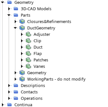
Assign tags to the new geometry parts so they are defined as
inputs for the mesh operations.
- Multi-select all the parts under the DuctGeometry composite and set Tags to Part_WrapperInputs.
- Expand the Surfaces node under each part of the DuctGeometry composite.
- Multi-select the node of the Adjuster, Clip, Flap, Patches, and Vanes parts and set Tags to Surface_DuctVanes.
-
Expand the part node and set Tags as
follows:
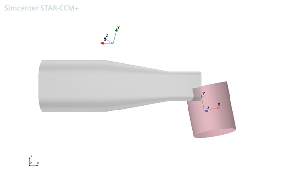
Node Tags External Surface_DuctExterior Internal Surface_DuctInterior After you assign the tags, the duct geometry is visible within the geometry representation of the simulation.
To locate the inflow volume, the vent refinement, the test
chamber, and the closures, open the scenes within the simulation
template.
-
To observe the location of the inflow volume, open the
01_inputGeometry scene.
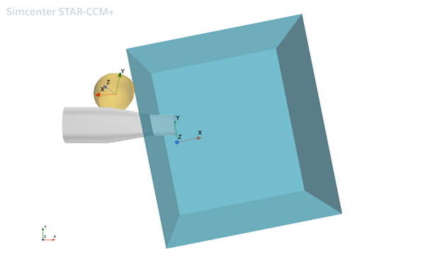
The inflow part does not align with the inlet of the duct. However, as the location of the inflow volume is defined with respect to the local DuctCenter coordinate system, you only need to adjust the parameters associated with this coordinate system to align the inflow volume.
-
Open the 02_Closures and 03_Vent
Refinement scenes to observe the extent to which the closures
and refinement region are misaligned.
02_Closures:
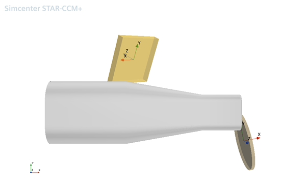
03_VentRefinement: