Defining Boundary Conditions
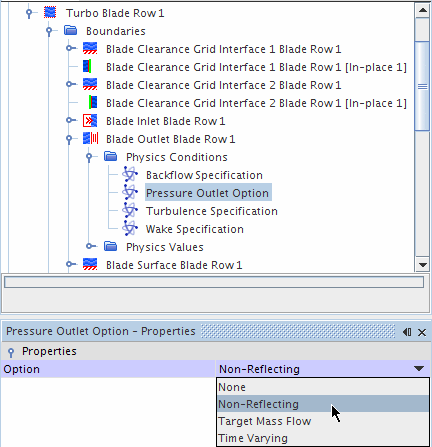
The Non-Reflecting option is activated for both the inlet and outlet boundaries.
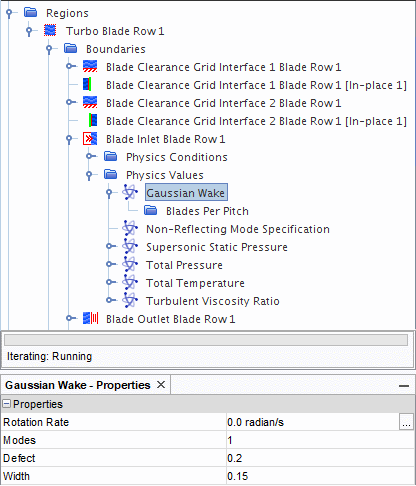
The Wake specification at the inlet is also set to define the periodic perturbation. This consists of defining the characteristics of the wake profile and the upstream blade row. In this example, a Gaussian wake profile is used, with a width of 0.15 and a defect of 2. The upstream blade row has 48 blades and is stationary (0.0 rads/s), as it represents a stator.
To define boundary conditions:
-
Expand the
node and set
Option to
Non-Reflecting.
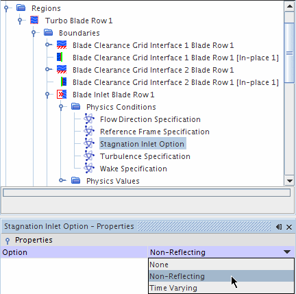
An additional node, , is added to the manager for this boundary when the Non-Reflecting option is activated.
-
Select the
node and set
Method to
.
In response to these changes, there are now two extra nodes in the folder that must be set.
-
Select the node, set Rotation Rate to
0.0 radian/s, and keep the default setting for
Modes as
1.
-
Select the
node and set
Number of Blades to
48.

-
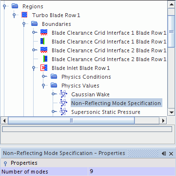
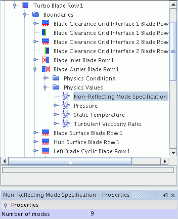
Select the node and set Number of Modes to
9.
-
Select
and set
Option to
Non-Reflecting.
-
For the same boundary, select the node and set Number of Modes to
9
-
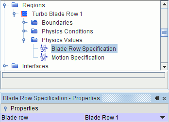
Select the
node and set
Blade Row to
.
- Save the simulation.