Gas Turbine Aerodynamics: Post-Processing
In turbomachinery studies, the analysis of the flow field throughout the blade passage requires advanced post processing methods.
Due to the complexity of the flow characteristics within a blade passage, it is often convenient to visualize data on parametric representations of the domain such as isosurfaces that are positioned parametrically in relation to the domain bounding surface, or as average surfaces and profiles at various stages within the flow domain. Parametric representations allow for consistent and repeatable post processing pipelines, even with different geometries.

To model this within Simcenter STAR-CCM+ a fluid physics continuum needs to be enabled. The fluid physics continuum contains the models required to fully define a steady turbulent flow of an ideal gas using the SST (Menter) K-Omega turbulence model along with the ideal gas model. To ensure the mass, momentum and energy continuity equations are solve simultaneously the coupled flow and coupled energy models are also enabled with the respective coupled implicit solver set the default values. Within the physics continuum the initial flow conditions are defined to allow for the progression of the simulation.
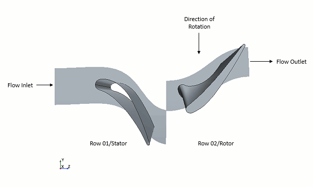
To allow for the boundary conditions of the problem to be defined two fluid regions are created (one for the stator, Row 01, and one for the rotor, Row 02). The total temperature, total pressure and flow angle have been defined at the inlet to the stator, while the static temperature has been defined at the pressure outlet of the rotor. The remaining boundaries have all been defined as wall boundaries except for the mixing plane and periodic interfaces.
To link the two regions together three separate interfaces have been defined. A periodic internal interface for the upper and lower surfaces of the stator region, An implicit mixing plane interface between the rows, and a periodic internal interface for the upper and lower surfaces of the rotor region. The periodic interface allows a row of blade in a turbomachine to be simulated using only one blade passage. The periodic interface accounts for this by mapping the data from the upper surface to the lower through a constant rotation. The mixing plane interface allows for the transfer of conserved quantities across the interface using circumferential averaging, which accounts for the difference in pitch of the 2 regions.