Projecting Isosurface Data to an Embedded Plane
In a highly-curved blade passage some areas of an isosurface can be obscured from view. To overcome this problem, you can project the isosurface onto a 2D plane located within the blade passage.
To apply the embedding transform:
- To make a copy of the Scalar: Blade to Blade scene, select the node and drag onto the Scenes node.
- Rename the copy to Scalar: Blade to Blade Projected.
- Right-click the node and select Delete.
- Select the Scalar 1 node and set Transform to Embedding: Axisymmetric 1 (Conformal).The conformal embedding transform uses the transform scheme. This transform scheme means that the values (which were calculated during the parameterization) are mapped to the x coordinate and the values are mapped to the y coordinate. This mapping ensures that the angles are conserved while the lengths are distorted.
- To view the projected results, in the Vis toolbar, click
 (Save-Restore-Select Views) and select The scene is as shown below:
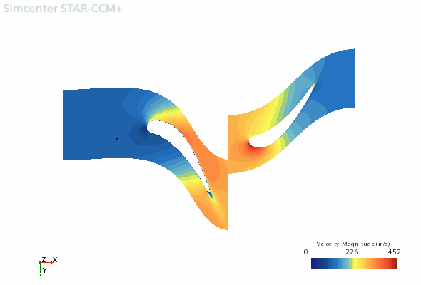
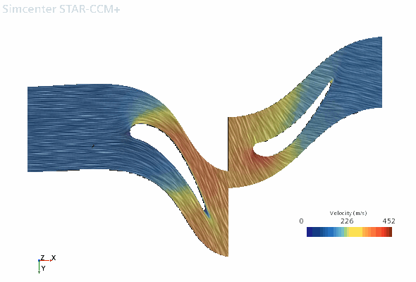
As well as visualizing the data as a scalar scene, you can also view data on an embedded vector scene:
- Right-click Scalar: Blade to Blade Projected and select .
- Expand the node and set the following properties:
Node Property Setting Vector 1 Display Mode Line Integral Convolution Transform Embedding: Axisymmetric 1 (Conformal)  Parts
PartsParts Vector FieldFunction - Right-click the node and select Toggle Visibility.
- To view the projected results, in the Vis toolbar, click (Save-Restore-Select Views) and select .The scene is shown below: