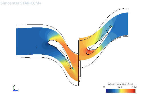
Viewing the Solution on a Blade-to-Blade Isosurface
A spanwise isosurface provides a surface of revolution at a specified spanwise position. Rendering solution data on this type of isosurface gives you an accurate picture of the flow behaviour across the blade rows in the passage.
Create a spanwise isosurface:
- Right-click the Derived Parts node and select
- Within the Edit dialog, set the following properties:
Property Setting Input Parts and Row 02 (default) Scalar Isovalue 0.5 Display No Displayer - Click Create then Close.
Create a new scalar scene:
- Right-click the Scenes node and select .
- Rename Scalar Scene 1 to Scalar: Blade to Blade.
- Select the node and set Parts to .
- In the Vis toolbar, click
 (Save-Restore-Select Views) and select .
 - Select the node and set Contour Style to Smooth Filled.
- Select the node and set Function to .The resulting scene looks as follows:
 The scene shows the velocity magnitude through the blade rows, between the hub and shroud walls. The Isovalue can be altered to view the flow features at any point along the spanwise direction. For example, to view the near hub the Isovalue is set to 0.1 and to view the near shroud the Isovalue is set to 0.9.