Setting Up Line Surfaces for Plotting
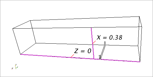
Create two parts by intersecting a plane with the bottom wall and symmetry plane boundary surfaces.
This results in the two line segments that are shown below.
To create a section:
- Click the Geometry Scene 1 tab in the Graphics window to activate it.
-
Right-click the node and select
A new interactive in-place dialog (Create Plane Section) appears.
-
Set the following values:
Box Property Value Input Parts Fluid: BottomWall Selected Plane Parameters Origin [0.0, 0.0, 1e-8] m Normal [0, 0, 1] m Display No Displayer Selected 
-
Click
Create, then click
Close.
A new derived part named is created.
- Rename this node to Z = 0
The section is offset slightly from the symmetry plane to make sure that realistic wall shear stress values are displayed.
Monitor the velocity along a line segment on the symmetry plane at x = 0.38 m. To create a section for this segment:
- For a second time, right-click the node and select
The in-place dialog appears.
-
Set the following values:
Box Property Value Input Parts Fluid: Symplane Selected Plane Parameters Origin [0.38, 0.0, 0.0] m Normal [1, 0, 0] m Display No Displayer Selected - Click Create, then click Close.
- Rename the new node to X = 0.38